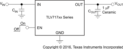
The TLV717P series of low-dropout (LDO) linear regulators are low quiescent current LDOs with excellent line and load transient performance and are designed for power-sensitive applications. These devices provide a typical accuracy of 0.5%.
The TLV717P series offer current foldback that throttles down the output current with a decrease in load resistance. The typical value at which current foldback initiates is 350 mA; the typical value of the output short current limit value is 40 mA.
Furthermore, these devices are stable with an effective output capacitance of only 0.1 µF. This feature enables the use of cost-effective capacitors that have higher bias voltages and temperature derating. The devices regulate to specified accuracy with no output load.
The TLV717P series is available in a 1-mm × 1-mm DQN package that makes them ideal for hand-held applications. The TLV717P provides an active pulldown circuit to quickly discharge output loads.
PART NUMBER | PACKAGE | BODY SIZE (NOM) |
---|---|---|
TLV717P | X2SON (4) | 1.00 mm × 1.00 mm |
Changes from A Revision (February 2012) to B Revision
Changes from * Revision (October 2011) to A Revision
PIN | I/O | DESCRIPTION | |
---|---|---|---|
NAME | NO. | ||
EN | 3 | I | Enable pin. Driving EN over 1.2 V turns on the regulator. Driving EN below 0.4 V puts the regulator into shutdown mode. |
GND | 2 | — | Ground pin |
IN | 4 | I | Input pin. A small capacitor is recommended from this pin to ground to assure stability. See the Input and Output Capacitor Requirements section in the Application and Implementation for more details. |
OUT | 1 | O | Regulated output voltage pin. A small 1-μF ceramic capacitor is recommended from this pin to ground to assure stability. See the Input and Output Capacitor Requirements section in the Application and Implementation for more details. |
Thermal pad | — | — | Connect to GND for improved thermal performance. |
MIN | MAX | UNIT | ||
---|---|---|---|---|
Voltage | Input range, VIN | –0.3 | 6 | V |
Enable range, VEN | –0.3 | VIN + 0.3 | ||
Output range, VOUT | –0.3 | 6 | ||
Current | Maximum output, IOUT | Internally limited | ||
Output short-circuit duration | Indefinite | |||
Continuous total power dissipation, PDISS | See Thermal Information | |||
Temperature | Junction, TJ | –55 | 150 | °C |
Storage junction, Tstg | –55 | 150 |
VALUE | UNIT | |||
---|---|---|---|---|
V(ESD) | Electrostatic discharge | Human-body model (HBM), per ANSI/ESDA/JEDEC JS-001(1) | ±2000 | V |
Charged-device model (CDM), per JEDEC specification JESD22-C101(2) | ±500 |
MIN | MAX | UNIT | ||
---|---|---|---|---|
VIN | Input voltage | 1.7 | 5.5 | V |
VOUT | Output voltage | 1.2 | 5 | V |
IOUT | Output current | 0 | 150 | mA |
VEN | Enable pin voltage | 0 | VIN | V |
TJ | Junction temperature | –40 | 85 | °C |
THERMAL METRIC | TLV717P | UNIT | |
---|---|---|---|
DQN (X2SON) | |||
4 PINS | |||
RθJA | Junction-to-ambient thermal resistance | 393.3 | °C/W |
RθJC(top) | Junction-to-case(top) thermal resistance | 140.3 | °C/W |
RθJB | Junction-to-board thermal resistance | 330 | °C/W |
ψJT | Junction-to-top characterization parameter | 6.5 | °C/W |
ψJB | Junction-to-board characterization parameter | 329 | °C/W |
RθJC(bot) | Junction-to-case(bottom) thermal resistance | 147.5 | °C/W |
The TLV717P belongs to a new family of next-generation value low-dropout (LDO) regulators. These devices consume low quiescent current and deliver excellent line and load transient performance. These characteristics, combined with low noise, very good PSRR with little (VIN – VOUT) headroom, make this family of devices ideal for RF portable applications.
This family of regulators offers current foldback. Device operating junction temperature is –40°C to 85°C.
The TLV717P has an internal foldback current limit that helps to protect the regulator during fault conditions. The current supplied by the device is gradually throttled down as the output voltage decreases. When the output is shorted, the LDO supplies a typical current of 40 mA. Output voltage is not regulated when the device is in current limit, and is VOUT = ILIMIT × RLOAD. The advantage of foldback current limit is that the ILIMIT value is less than the fixed current limit. Therefore, the power that the PMOS pass transistor dissipates [(VIN – VOUT) × ILIMIT] is much less.
The TLV717P PMOS pass element has a built-in body diode that conducts current when the voltage at OUT exceeds the voltage at IN. This current is not limited, so if extended reverse voltage operation is anticipated, external limiting to 5% of the rated output current is recommended.
The enable pin (EN) is active high. The device is enabled when the voltage at the EN pin goes above 0.9 V. This relatively lower voltage value required to turn the LDO on can be exploited to power the LDO with a GPIO of recent processors whose GPIO logic 1 voltage level is lower than traditional microcontrollers. The device is turned off when the EN pin is held at less than 0.4 V. When shutdown capability is not required, EN can be connected to the IN pin.
The TLV717P uses an undervoltage lockout circuit (UVLO = 1.6 V) to keep the output shut off until the internal circuitry operates properly.
The device regulates to the nominal output voltage under the following conditions:
If the input voltage is lower than the nominal output voltage plus the specified dropout voltage, but all other conditions are met for normal operation, the device operates in dropout mode. In this condition, the output voltage is the same the input voltage minus the dropout voltage. The transient performance of the device is significantly degraded because the pass device is in a triode state and no longer controls the current through the LDO. Line or load transients in dropout may result in large output voltage deviations.
The device is disabled under the following conditions:
When the device is disabled, the active pulldown resistor discharges the output.
Table 1 lists the conditions that lead to the different modes of operation.
OPERATING MODE | PARAMETER | ||
---|---|---|---|
VIN | VEN | IOUT | |
Normal mode | VIN > VOUT(nom) + VDO
and VIN > UVLORISE |
VEN > VEN(HI) | IOUT < ILIM |
Dropout mode | UVLORISE < VIN < VOUT(nom) + VDO | VEN > VEN(HI) | IOUT < ILIM |
Disabled mode (any true condition disables the device) |
VIN < UVLOFALL | VEN < VEN(LO) | — |
NOTE
Information in the following applications sections is not part of the TI component specification, and TI does not warrant its accuracy or completeness. TI’s customers are responsible for determining suitability of components for their purposes. Customers should validate and test their design implementation to confirm system functionality.
The TLV717P is a low-dropout regulator (LDO) with low quiescent current that delivers excellent line and load transient performance. This LDO regulator offers a foldback current limit. The operating junction temperature of this device series is –40°C to 85°C.
Table 2 lists the parameters for this application.
PARAMETER | DESIGN REQUIREMENT |
---|---|
Input voltage | 3.8 V |
Output voltage | 2.8 V ±1% |
Output current | 30 to 150 mA |
TI recommends X5R- and X7R-type ceramic capacitors because they have minimal variation in value and equivalent series resistance (ESR) over temperature. The TLV717P is designed to be stable with an effective capacitance of 0.1 µF or larger at the output, though TI recommends a 1-µF ceramic capacitor for typical applications. Thus, the device is stable with capacitors of other dielectric types as well, as long as the effective capacitance under operating bias voltage and temperature is greater than 0.1 µF. This effective capacitance refers to the capacitance that the LDO detects under operating bias voltage and temperature conditions; that is, the capacitance after taking both bias voltage and temperature derating into consideration. In addition to allowing the use of cheaper dielectrics, this capability of being stable with 0.1-µF effective capacitance also enables the use of smaller footprint capacitors that have higher derating in size- and space-constrained applications. Using a 0.1-µF rated capacitor at the LDO output does not ensure stability because the effective capacitance under the specified operating conditions would be less than 0.1 µF. Maximum ESR should be less than 200 mΩ.
Although an input capacitor is not required for stability, it is good analog design practice to connect a 0.1-µF to 1-µF, low ESR capacitor across the IN and GND pins of the regulator. This capacitor counteracts reactive input sources and improves transient response, noise rejection, and ripple rejection. A higher-value capacitor may be necessary if large, fast, rise-time load transients are anticipated, or if the device is not located close to the power source. If source impedance is more than 2 Ω, a 0.1-µF input capacitor may be necessary to ensure stability.
The TLV717P uses a PMOS pass transistor to achieve low dropout. When (VIN – VOUT) is less than the dropout voltage (VDO), the PMOS pass device is in the linear region of operation and the input-to-output resistance is the RDS(ON) of the PMOS pass element. VDO scales approximately with output current because the PMOS device behaves like a resistor in dropout. As with any linear regulator, PSRR and transient response are degraded as (VIN – VOUT) approaches dropout.
As with any regulator, increasing the size of the output capacitor reduces over- and undershoot magnitude but increases the duration of the transient response.