JAJSMO7D August 2021 – September 2022 TMAG5231
PRODUCTION DATA
- 1 特長
- 2 アプリケーション
- 3 概要
- 4 Revision History
- 5 Device Comparison
- 6 Pin Configuration and Functions
- 7 Specifications
- 8 Detailed Description
- 9 Application and Implementation
- 10Device and Documentation Support
- 11Mechanical and Packaging Information
パッケージ・オプション
メカニカル・データ(パッケージ|ピン)
サーマルパッド・メカニカル・データ
- DMR|4
発注情報
9.1.1 Defining the Design Implementation
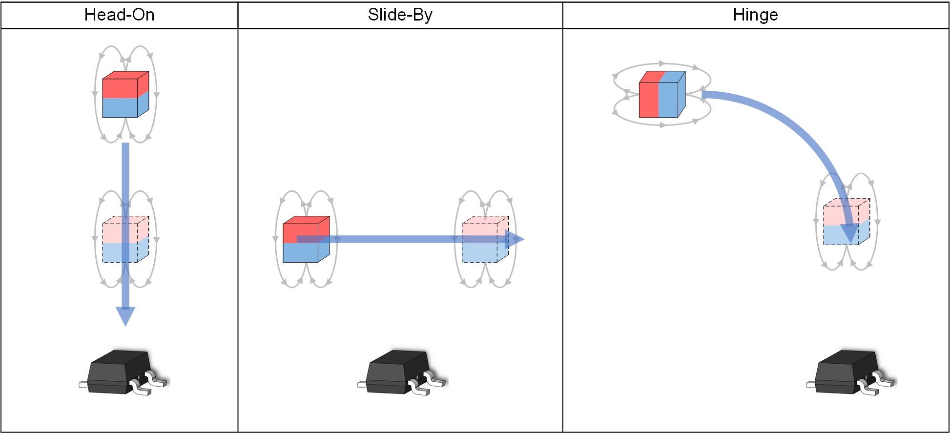
The first step of design is identifying your general design implementation, which means you will define whether you are detecting a magnet sliding past the sensor, moving head-on toward the sensor, or swinging toward the sensor on a hinge. Figure 9-1 shows examples for each of the aforementioned design implementations.
 Figure 9-1 Design Implementations
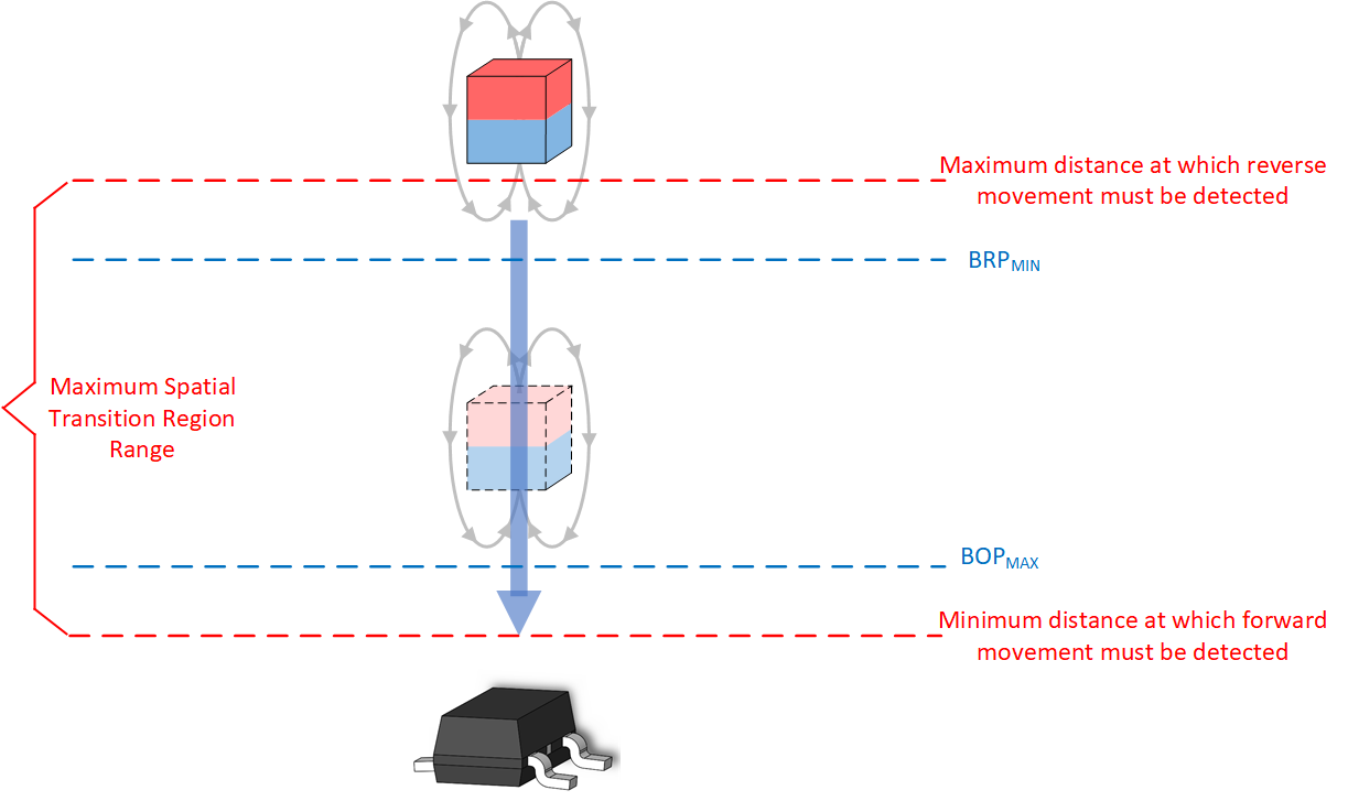
With each implementation, the objective is to design the system such that the spatial coordinates of the transition region fall within the spatial coordinates associated with the BOP maximum and BRP minimum specifications. Figure 9-2 shows a head-on example that shows how the location corresponding to the device BOPMAX and BRPMIN fall within the desired transition region. To facilitate rapid design iteration, TI’s Magnetic Sensing Proximity Tool is leveraged in the following design examples.
 Figure 9-2 Head-On Example