JAJSJW0E September 2020 – July 2024 TMUX6219
PRODUCTION DATA
- 1
- 1 特長
- 2 アプリケーション
- 3 概要
- 4 Pin Configuration and Functions
-
5 Specifications
- 5.1 Absolute Maximum Ratings
- 5.2 ESD Ratings
- 5.3 Thermal Information
- 5.4 Recommended Operating Conditions
- 5.5 Source or Drain Continuous Current
- 5.6 ±15 V Dual Supply: Electrical Characteristics
- 5.7 ±15 V Dual Supply: Switching Characteristics
- 5.8 36 V Single Supply: Electrical Characteristics
- 5.9 36 V Single Supply: Switching Characteristics
- 5.10 12 V Single Supply: Electrical Characteristics
- 5.11 12 V Single Supply: Switching Characteristics
- 5.12 +5 V / -8 V Dual Supply: Electrical Characteristics
- 5.13 +5 V / -8 V Dual Supply: Switching Characteristics
- 5.14 ±5 V Dual Supply: Electrical Characteristics
- 5.15 ±5 V Dual Supply: Switching Characteristics
- 5.16 Typical Characteristics
-
6 Parameter Measurement Information
- 6.1 On-Resistance
- 6.2 Off-Leakage Current
- 6.3 On-Leakage Current
- 6.4 Transition Time
- 6.5 tON(EN) and tOFF(EN)
- 6.6 Break-Before-Make
- 6.7 tON (VDD) Time
- 6.8 Propagation Delay
- 6.9 Charge Injection
- 6.10 Off Isolation
- 6.11 Crosstalk
- 6.12 Bandwidth
- 6.13 THD + Noise
- 6.14 Power Supply Rejection Ratio (PSRR)
- 7 Detailed Description
- 8 Application and Implementation
- 9 Power Supply Recommendations
- 10Layout
- 11Device and Documentation Support
- 12Revision History
- 13Mechanical, Packaging, and Orderable Information
パッケージ・オプション
メカニカル・データ(パッケージ|ピン)
サーマルパッド・メカニカル・データ
発注情報
3 概要
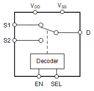
TMUX6219 は、シングル チャネル、2:1 (SPDT) 構成の CMOS スイッチです。このデバイスは単一電源 (4.5V~36V)、デュアル電源 (±4.5V~±18V)、または非対称電源 (VDD = 5V、VSS = -8V など) で適切に動作します。TMUX6219 は、ソース (Sx) およびドレイン (D) ピンで、VSS から VDD までの範囲の双方向アナログおよびデジタル信号をサポートします。
TMUX6219 は、EN ピンの制御によりイネーブルまたはディスエーブルにできます。ディスエーブルのときは、両方の信号経路のスイッチがオフになります。イネーブルのとき、SEL ピンを使用して信号経路 1 (S1 から D へ) または信号経路 2 (S2 から D へ) をオンにできます。すべてのロジック制御入力は、1.8V~VDD のロジック レベルをサポートしており、有効な電源電圧範囲で動作している場合、TTL ロジックと CMOS ロジックの両方の互換性を確保できます。フェイルセーフ ロジック回路により、電源ピンよりも先に制御ピンに電圧が印加されるため、デバイスへの損傷の可能性が避けられます。
TMUX6219 は、高精度スイッチおよびマルチプレクサのデバイス ファミリの製品です。これらのデバイスは、オンおよびオフ時のリーク電流が非常に小さく、電荷注入も少ないため、高精度の測定アプリケーションに使用できます。
(1) 詳細については、セクション 13 を参照してください。
(2) パッケージ サイズ (長さ×幅) は公称値であり、該当する場合はピンも含まれます。
 TMUX6219 ブロック図