JAJSIM3C March   2020  – May 2024 TPA6211T-Q1

PRODUCTION DATA  

  1.   1
  2. 特長
  3. アプリケーション
  4. 概要
  5. Pin Configuration and Functions
  6. Specifications
    1. 5.1 Absolute Maximum Ratings
    2. 5.2 ESD Ratings
    3. 5.3 Recommended Operating Conditions
    4. 5.4 Thermal Information
    5. 5.5 Electrical Characteristics
    6. 5.6 Operating Characteristics
    7. 5.7 Dissipation Ratings
    8.     Typical Characteristics
  7. Detailed Description
    1. 6.1 Overview
    2. 6.2 Functional Block Diagram
    3. 6.3 Feature Description
      1. 6.3.1 Advantages of Fully Differential Amplifiers
      2. 6.3.2 Fully Differential Amplifier Efficiency and Thermal Information
      3. 6.3.3 Differential Output Versus Single-Ended Output
    4. 6.4 Device Functional Modes
  8. Application and Implementation
    1. 7.1 Application Information
    2. 7.2 Typical Applications
      1. 7.2.1 Typical Differential Input Application
        1. 7.2.1.1 Design Requirements
        2. 7.2.1.2 Detailed Design Procedure
          1. 7.2.1.2.1 Resistors (RI)
          2. 7.2.1.2.2 Bypass Capacitor (CBYPASS) and Start-Up Time
          3. 7.2.1.2.3 Input Capacitor (CI)
          4. 7.2.1.2.4 Band-Pass Filter (RI, CI, and CF)
            1. 7.2.1.2.4.1 Step 1: Low-Pass Filter
            2. 7.2.1.2.4.2 Step 2: High-Pass Filter
            3. 7.2.1.2.4.3 Step 3: Additional Low-Pass Filter
          5. 7.2.1.2.5 Decoupling Capacitor (CS)
          6. 7.2.1.2.6 Using Low-ESR Capacitors
        3. 7.2.1.3 Application Curves
      2. 7.2.2 Other Application Circuits
    3. 7.3 Power Supply Recommendations
      1. 7.3.1 Power Supply Decoupling Capacitor
    4. 7.4 Layout
      1. 7.4.1 Layout Guidelines
      2. 7.4.2 Layout Example
  9. Device and Documentation Support
    1. 8.1 Receiving Notification of Documentation Updates
    2. 8.2 Community Resources
    3. 8.3 Trademarks
  10. Revision History
  11. 10Mechanical, Packaging, and Orderable Information

パッケージ・オプション

メカニカル・データ(パッケージ|ピン)
サーマルパッド・メカニカル・データ
発注情報

概要

TPA6211T-Q1 デバイスは、ほとんどの用途でプリント基板 (PCB) の占有面積がわずか 20mm2 でありながら、最低 3Ω のインピーダンスのスピーカを駆動するように設計された 3.1W モノラル完全差動アンプです。本デバイスは 2.5V~5.5V で動作し、静止電流はわずか 4mA です。TPA6211T-Q1 デバイスは省スペースの 8 ピン HVSSOP パッケージで供給されます。

20Hz~2kHz で 80dB の電源電圧除去比、RF 整流耐性の向上、小さな PCB 占有面積、最小限のポップ音での高速起動といった特長を持つ TPA6211T-Q1 デバイスは、緊急通報用途に優れた選択肢です。また、クラスタ チャイムやドライバーへの通知機能など、インフォテインメント / クラスタ用途の低消費電力ニーズにも対応します。

製品情報
部品番号 パッケージ (1) パッケージ サイズ(2) 本体サイズ (公称)
TPA6211T-Q1 HVSSOP (8) 3mm × 4.9mm 3mm × 3mm
利用可能なすべてのパッケージについては、データシートの末尾にある注文情報を参照してください。
パッケージ サイズ (長さ × 幅) は公称値であり、該当する場合はピンも含まれます。
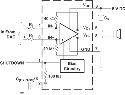
TPA6211T-Q1 アプリケーション回路
C(BYPASS) の接続は任意です
アプリケーション回路