JAJSHM7B June 2019 – November 2021 TPS1HB50-Q1
PRODUCTION DATA
- 1 特長
- 2 アプリケーション
- 3 概要
- 4 Revision History
- 5 Device Comparison Table
- 6 Pin Configuration and Functions
- 7 Specifications
- 8 Parameter Measurement Information
-
9 Detailed Description
- 9.1 Overview
- 9.2 Functional Block Diagram
- 9.3
Feature Description
- 9.3.1 Protection Mechanisms
- 9.3.2 Diagnostic Mechanisms
- 9.4 Device Functional Modes
- 10Application and Implementation
- 11Power Supply Recommendations
- 12Layout
- 13Device and Documentation Support
- 14Mechanical, Packaging, and Orderable Information
パッケージ・オプション
メカニカル・データ(パッケージ|ピン)
- PWP|16
サーマルパッド・メカニカル・データ
- PWP|16
発注情報
9.3.1.4 Reverse Battery
In the reverse battery condition, the switch will automatically be enabled regardless of the state of EN to prevent excess power dissipation inside the MOSFET body diode. In many applications (for example, resistive loads), the full load current can be present during reverse battery. In order to activate the automatic switch on feature, SEL must have a path to ground from either from the MCU or it needs to be tied to ground through RPROT if unused.
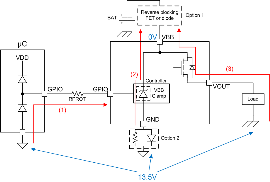
There are two options for blocking reverse current in the system. The first option is to place a blocking device (FET or diode) in series with the battery supply, blocking all current paths. The second option is to place a blocking diode in series with the GND node of the high-side switch. This method will protect the controller portion of the switch (path 2), but it will not prevent current from flowing through the load (path 3). The diode used for the second option can be shared amongst multiple high-side switches.
Path 1 shown in Figure 9-4 is blocked inside of the device.
 Figure 9-4 Current Path During Reverse Battery
For more information on reverse battery protection, refer to TI's Reverse Battery Protection for High Side Switches application note.