JAJSJN2D November 2007 – October 2020 TPS2041B-Q1 , TPS2042B-Q1 , TPS2051B-Q1
PRODUCTION DATA
- 1 特長
- 2 アプリケーション
- 3 概要
- 4 Revision History
- 5 Pin Configuration and Functions
- 6 Specifications
- 7 Parameter Measurement Information
- 8 Detailed Description
- 9 Application and Implementation
- 10Power Supply Recommendations
- 11Layout
- 12Device and Documentation Support
- 13Mechanical, Packaging, and Orderable Information
9.2.3 Generic Hot-Plug Applications
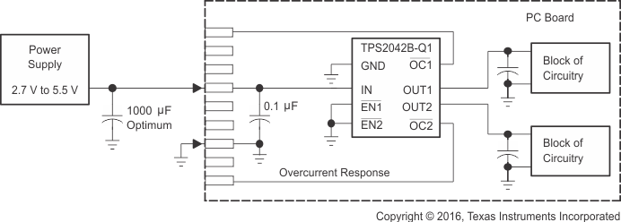
In many applications, it may be necessary to remove modules or PC boards while the main unit is still operating. These are considered hot-plug applications. Such implementations require the control of current surges seen by the main power supply and the card being inserted. The most effective way to control these surges is to limit and slowly ramp the current and voltage being applied to the card, similar to the way in which a power supply normally turns on. Due to the controlled rise and fall times of the TPS204xB-Q1 and TPS205xB-Q1, these devices can be used to provide a softer start-up to devices being hot-plugged into a powered system. The UVLO feature of the TPS204xB-Q1 and TPS205xB-Q1 also ensures that the switch is off after the card has been removed, and that the switch is off during the next insertion. The UVLO feature ensures a soft start with a controlled rise time for every insertion of the card or module.
 Figure 9-15 Example Hot-Plug Implementation (TPS2042B-Q1)
By placing the TPS204xB-Q1 or TPS205xB-Q1 between the VCC input and the rest of the circuitry, the input power reaches these devices first after insertion. The typical rise time of the switch is approximately 1 ms, providing a slow voltage ramp at the output of the device. This implementation controls system surge currents and provides a hot-plugging mechanism for any device.