SLVSCC8A May 2014 – December 2014 TPS2513A-Q1 , TPS2514A-Q1
PRODUCTION DATA.
7 Detailed Description
7.1 Overview
TPS2513A-Q1 and TPS2514A-Q1 are dedicated charging port controllers, used for the charging of most popular mobile phones and tablets.
The following overview references various industry standards. It is always recommended to consult the latest standard to ensure the most recent and accurate information.
Rechargeable portable equipment requires an external power source to charge its batteries. USB ports are convenient locations for charging because of an available 5-V power source. Universally accepted standards are required to ensure host and client-side devices meet the power management requirements. Traditionally, USB host ports following the USB 2.0 Specification must provide at least 500 mA to downstream client-side devices. Because multiple USB devices can be attached to a single USB port through a bus-powered hub, it is the responsibility of the client-side device to negotiate the power allotment from the host to guarantee the total current draw does not exceed 500 mA. In general, each USB device can subsequently request more current, which is granted in steps of 100 mA up 500 mA total. The host may grant or deny the request based on the available current.
Additionally, the success of the USB technology makes the micro-USB connector a popular choice for wall adapter cables. This allows a portable device to charge from both a wall adapter and USB port with only one connector.
One common difficulty has resulted from this. As USB charging has gained popularity, the 500-mA minimum defined by the USB 2.0 Specification or 900 mA defined in the USB 3.0 Specification, has become insufficient for many handsets, tablets and personal media players (PMP) which have a higher rated charging current. Wall adapters and car chargers can provide much more current than 500 mA or 900 mA to fast charge portable devices. Several new standards have been introduced defining protocol handshaking methods that allow host and client devices to acknowledge and draw additional current beyond the 500 mA (defined in the USB 2.0 Specification) or 900 mA (defined in the USB 3.0 Specification) minimum while using a single micro-USB input connector.
7.2 Functional Block Diagram
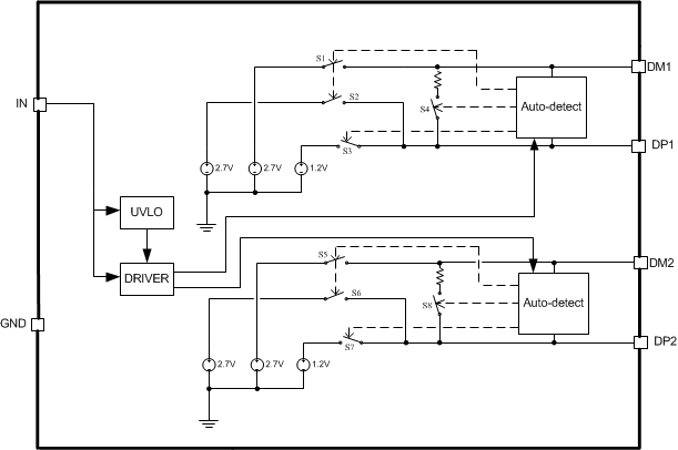
 Figure 4. TPS2513A-Q1 Functional Block Diagram
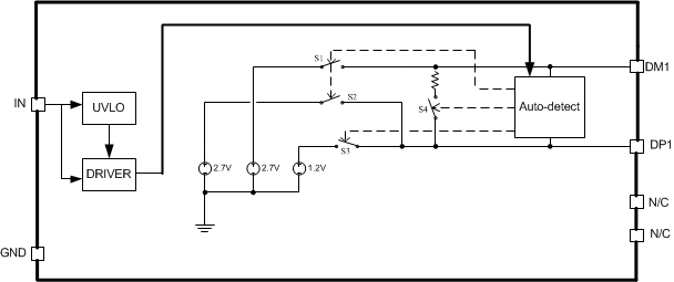
 Figure 5. TPS2514A-Q1 Functional Block Diagram
7.3 Feature Description
7.3.1 BC1.2
TPS2513A-Q1 and TPS2514A-Q1 support four of the most common protocols:
- USB Battery Charging Specification, Revision 1.2 (BC1.2)
- Chinese Telecommunications Industry Standard YD/T 1591-2009
- Divider Mode
- 1.2 V Mode
YD/T 1591-2009 is a subset of the BC1.2 specification supported by the vast majority of devices that implement USB charging. Divider and 1.2-V charging schemes are supported in devices from specific yet popular device makers. BC1.2 has three different port types, listed as follows.
- Standard downstream port (SDP)
- Charging downstream port (CDP)
- Dedicated charging port (DCP)
The BC1.2 Specification defines a charging port as a downstream facing USB port that provides power for charging portable equipment.
Table 1 shows different port operating modes according to the BC1.2 Specification.
Table 1. Operating Modes Table
| PORT TYPE | SUPPORTS USB2.0 COMMUNICATION |
MAXIMUM ALLOWABLE CURRENT DRAWN BY PORTABLE EQUIPMENT (A) |
|---|---|---|
| SDP (USB 2.0) | Yes | 0.5 |
| SDP (USB 3.0) | Yes | 0.9 |
| CDP | Yes | 1.5 |
| DCP | No | 1.5 |
The BC1.2 Specification defines the protocol necessary to allow portable equipment to determine what type of port it is connected to so that it can allot its maximum allowable current drawn. The hand-shaking process is two steps. During step one, the primary detection, the portable equipment outputs a nominal 0.6 V output on its D+ line and reads the voltage input on its D– line. The portable device concludes it is connected to a SDP if the voltage is less than the nominal data detect voltage of 0.3 V. The portable device concludes that it is connected to a Charging Port if the D– voltage is greater than the nominal data detect voltage of 0.3V and less than 0.8 V. The second step, the secondary detection, is necessary for portable equipment to determine between a CDP and a DCP. The portable device outputs a nominal 0.6 V output on its D– line and reads the voltage input on its D+ line. The portable device concludes it is connected to a CDP if the data line being remains is less than the nominal data detect voltage of 0.3 V. The portable device concludes it is connected to a DCP if the data line being read is greater than the nominal data detect voltage of 0.3 V and less than 0.8 V.
7.3.2 Undervoltage Lockout (UVLO)
The undervoltage lockout (UVLO) circuit disables DP1, DM1, DP2 and DM2 output voltage until the input voltage reaches the UVLO turn-on threshold. Built-in hysteresis prevents unwanted oscillations due to input voltage drop from large current surges.
7.3.3 DCP Auto-Detect
TPS2513A-Q1 and TPS2514A-Q1 integrate an auto-detect feature to support Divider 3 mode, shorted mode and 1.2 V modes. If a divider device is attached, 2.7 V is applied to the DP pin and 2.7 V is applied to the DM pin. If a BC1.2-compliant device is attached, the TPS251xA-Q1 automatically switches into shorted mode. If a device compliant with the 1.2 V / 1.2 V charging scheme is attached, 1.2 V is applied on both the DP pin and the DM pin. The functional diagram of DCP auto-detect feature (DM1 and DP1) is shown in Figure 6. DCP auto-detect feature (DM2 and DP2) has the same functional configuration.
 Figure 6. DCP Auto-Detect Functional Diagram
7.4 Device Functional Modes
7.4.1 Shorted Mode
The USB BC1.2 Specification and the Chinese Telecommunications Industry Standard YD/T 1591-2009 specify that the D+ and D– data lines should be shorted together with a maximum series impedance of 200 Ω. This is shown in Figure 7.
 Figure 7. Shorted Mode
7.4.2 Divider Mode
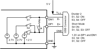
There are three charging schemes for divider mode. They are named after Divider 1, Divider 2, and Divider 3 that are shown in Figure 8, Figure 9, and Figure 10. The Divider 1 charging scheme is used for 5-W adapters, and applies 2 V to the D+ line and 2.7 V to the D– data line. The Divider 2 charging scheme is used for 10-W adapters, and applies 2.7 V on the D+ line and 2 V is applied on the D– line. The Divider 3 charging scheme is used for 12-W adapters, and applies 2.7 V on D+ and D- lines. TPS2513A-Q1 and TPS2514A-Q1 only integrate Divider 3 charging scheme.
 Figure 8. Divider 1
 Figure 10. Divider 3
 Figure 9. Divider 2
7.4.3 1.2 V Mode
As shown in Figure 11, some tablet USB chargers require 1.2 V on the shorted data lines of the USB connector. The maximum resistance between the D+ line and the D- line is 200 Ω.
 Figure 11. 1.2 V Mode
The device is a USB dedicated charging port (DCP) controllers. Applications include vehicle power charger, wall adapters with USB DCP and other USB chargers. The device DCP controllers have the auto-detect feature that monitors the D+ and D– line voltages of the USB connector, providing the correct electrical signatures on the DP and DM pins for the correct detections of compliant portable devices to fast charge. These portable devices include smart phones, 5-V tablets and personal media players.