-
TPS254900-Q1 車載用USBホスト充電器、VBATTへの短絡保護機能搭載
- 1 特長
- 2 アプリケーション
- 3 概要
- 4 改訂履歴
- 5 Pin Configuration and Functions
- 6 Specifications
- 7 Parameter Measurement Information
-
8 Detailed Description
- 8.1 Overview
- 8.2 Functional Block Diagram
- 8.3 Feature Description
- 8.4 Device Functional Modes
- 9 Application and Implementation
- 10Power Supply Recommendations
- 11Layout
- 12デバイスおよびドキュメントのサポート
- 13メカニカル、パッケージ、および注文情報
- 重要なお知らせ
DATA SHEET
TPS254900-Q1 車載用USBホスト充電器、VBATTへの短絡保護機能搭載
このリソースの元の言語は英語です。 翻訳は概要を便宜的に提供するもので、自動化ツール (機械翻訳) を使用していることがあり、TI では翻訳の正確性および妥当性につきましては一切保証いたしません。 実際の設計などの前には、ti.com で必ず最新の英語版をご参照くださいますようお願いいたします。
1 特長
- 下記内容でAEC-Q100認定済み
- デバイスHBM ESD分類レベルH2
- デバイスCDM ESD分類レベルC5
- 入力電圧範囲: 4.5V~6.5V
- 45mΩ(標準値)の ハイサイドMOSFETを内蔵
- 最大連続出力電流: 3A
- コネクタでVBUS ±5%のケーブル補償精度
- USB BC 1.2 CDPおよびSDPモードをサポート
- OUT、DP_IN、DM_INピンのバッテリ短絡保護
- DP_INとDM_INはIEC 61000-4-2規格に準拠
- ±8kV接触および±15kV空中放電
- 3mm×4mmの20ピンQFNパッケージ
2 アプリケーション
- 車載用USB充電ポート(ホストおよびハブ)
- 車載用USB保護
3 概要
TPS254900-Q1デバイスはUSB充電ポート・コントローラおよびパワー・スイッチで、バッテリ短絡保護機能を備えています。この機能により、OUT、DM_IN、DP_INが保護されます。これら3本のピンは、18Vまでの電圧に耐えられます。バッテリへの短絡状況が発生すると、内部のMOSFETが迅速にオフになります。この迅速なオフは、上流のDC/DCコンバータ、プロセッサ、ハブ・データ・ラインを保護するため非常に重要です。
TPS254900-Q1 45mΩパワー・スイッチには2つの選択可能な可変の電流制限があり、隣接するポートに重い負荷が発生している場合に電流制限値を低く調整し、ポートの電力を管理できます。これは、複数のポートを持つシステムや、上流の電源の容量が限られている場合に重要です。
TPS254900-Q1には電流センス出力があり、上流の電源を制御して、大きな充電電流が供給されている場合でも、USBポートで5Vを維持できます。この機能は、USBケーブルが長く、高速充電を行う携帯機器によって大きな電圧低下が発生するようなシステムで重要です。
電流モニタにより、システムはIMON電圧を監視して、負荷電流をリアルタイムで監視できます。この電流モニタは非常に便利で、動的なポート電力管理にも使用できます。
また、TPS254900-Q1デバイスはDP_INおよびDM_INについて、IEC 61000-4-2、レベル4準拠のESD保護機能を備えています。
製品情報(1)
| 型番 | パッケージ | 本体サイズ(公称) |
|---|---|---|
| TPS254900-Q1 | WQFN (20) | 3.00mm×4.00mm |
- 利用可能なすべてのパッケージについては、このデータシートの末尾にある注文情報を参照してください。
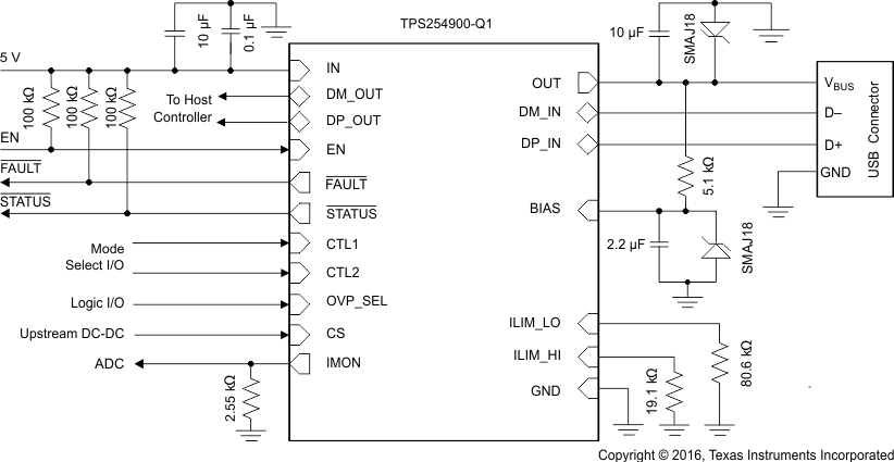
回路図

5 Pin Configuration and Functions
RVC Package
20-Pin WQFN
Top View
Pin Functions
| PIN | TYPE(1) | DESCRIPTION | |
|---|---|---|---|
| NAME | NO. | ||
| BIAS | 12 | PWR | Used for IEC protection. Typically, connect a 2.2-µF capacitor and a transient-voltage suppressor (TVS) to ground and 5.1 kΩ to OUT. |
| CS | 6 | O | Linear cable compensation current. Connect to divider resistor of front-end dc-dc converter. |
| CTL1 | 8 | I | Logic-level control input for controlling the charging mode and the signal switches; see the Device Truth Table (TT). |
| CTL2 | 9 | I | Logic-level control input for controlling the charging mode and the signal switches; see the Device Truth Table (TT). |
| DM_IN | 14 | I/O | D– data line to downstream connector |
| DM_OUT | 4 | I/O | D– data line to upstream USB host controller |
| DP_IN | 13 | I/O | D+ data line to downstream connector |
| DP_OUT | 5 | I/O | D+ data line to upstream USB host controller |
| EN | 7 | I | Logic-level control input for turning the power and signal switches on or off. When EN is low, the device is disabled, and the signal and power switches are OFF. |
| FAULT | 18 | O | Active-low, open-drain output, asserted during overtemperature, overcurrent, and overvoltage conditions. |
| GND | 11 | — | Ground connection; should be connected externally to the thermal pad. |
| ILIM_HI | 20 | I | External resistor used to set the high current-limit threshold. |
| ILIM_LO | 19 | I | External resistor used to set the low current-limit threshold and the load-detection current threshold. |
| IMON | 1 | O | This pin sources a scaled-down ratio of current through the internal FET. A resistor from this pin to GND converts current to proportional voltage; used as an analog current monitor. |
| IN | 2,3 | PWR | Input supply voltage; connect a 0.1-µF or greater ceramic capacitor from IN to GND as close to the IC as possible. |
| OUT | 15,16 | PWR | Power-switch output |
| OVP_SEL | 10 | I | Logic-level control input for choosing the OUT overvoltage threshold. When OVP_SEL is low, V(OV_OUT_LOW) is active. When OVP_SEL is high, V(OV_OUT_HIGH) is active. |
| STATUS | 17 | O | Active-low open-drain output, asserted in load-detect conditions |
| Thermal pad | — | — | Thermal pad on the bottom of the package |
(1) I = Input, O = Output, I/O = Input and output, PWR = Power