JAJSRT8A October 2023 – March 2024 TPS25751
PRODUCTION DATA
- 1
- 1 特長
- 2 アプリケーション
- 3 概要
- 4 Device Comparison Table
- 5 Pin Configuration and Functions
-
6 Specifications
- 6.1 Absolute Maximum Ratings
- 6.2 ESD Ratings
- 6.3 Recommended Operating Conditions
- 6.4 Recommended Capacitance
- 6.5 Thermal Information
- 6.6 Power Supply Characteristics
- 6.7 Power Consumption
- 6.8 PP_5V Power Switch Characteristics
- 6.9 PPHV Power Switch Characteristics - TPS25751D
- 6.10 PP_EXT Power Switch Characteristics - TPS25751S
- 6.11 Power Path Supervisory
- 6.12 CC Cable Detection Parameters
- 6.13 CC VCONN Parameters
- 6.14 CC PHY Parameters
- 6.15 Thermal Shutdown Characteristics
- 6.16 ADC Characteristics
- 6.17 Input/Output (I/O) Characteristics
- 6.18 BC1.2 Characteristics
- 6.19 I2C Requirements and Characteristics
- 6.20 Typical Characteristics
- 7 Parameter Measurement Information
-
8 Detailed Description
- 8.1 Overview
- 8.2 Functional Block Diagram
- 8.3
Feature Description
- 8.3.1 USB-PD Physical Layer
- 8.3.2 Power Management
- 8.3.3 Power Paths
- 8.3.4 Cable Plug and Orientation Detection
- 8.3.5 Overvoltage Protection (CC1, CC2)
- 8.3.6 Default Behavior Configuration (ADCIN1, ADCIN2)
- 8.3.7 ADC
- 8.3.8 BC 1.2 (USB_P, USB_N)
- 8.3.9 Digital Interfaces
- 8.3.10 Digital Core
- 8.3.11 I2C Interface
- 8.4 Device Functional Modes
- 8.5 Thermal Shutdown
-
9 Application and Implementation
- 9.1 Application Information
- 9.2 Typical Application
- 9.3 Power Supply Recommendations
- 9.4
Layout
- 9.4.1 TPS25751D - Layout
- 9.4.2 TPS25751S - Layout
- 10Device and Documentation Support
- 11Revision History
- 12Mechanical, Packaging, and Orderable Information
パッケージ・オプション
メカニカル・データ(パッケージ|ピン)
サーマルパッド・メカニカル・データ
- RSM|32
発注情報
8.3.2 Power Management
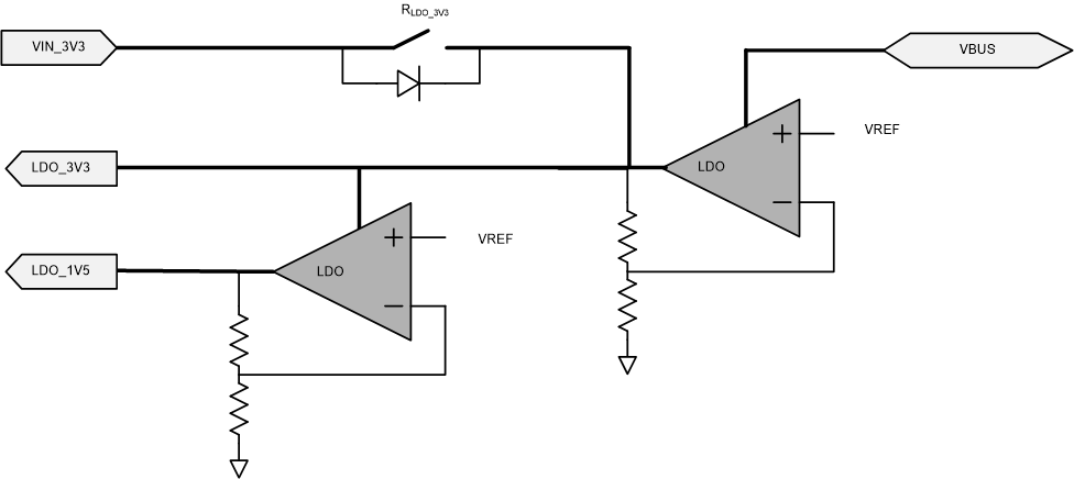
The TPS25751 power management block receives power and generates voltages to provide power to the TPS25751 internal circuitry. These generated power rails are LDO_3V3 and LDO_1V5. LDO_3V3 can also be used as a low power output for external EEPROM memory. The power supply path is shown in Figure 8-11.
 Figure 8-11 Power
Supplies
Figure 8-11 Power
SuppliesThe TPS25751 is powered from either VIN_3V3 or VBUS. The normal power supply input is VIN_3V3. When powering from VIN_3V3, current flows from VIN_3V3 to LDO_3V3 to power the core 3.3-V circuitry and I/Os. A second LDO steps the voltage down from LDO_3V3 to LDO_1V5 to power the 1.5-V core digital circuitry. When VIN_3V3 power is unavailable and power is available on VBUS, it is referred to as the dead-battery start-up condition. In a dead-battery start-up condition, the TPS25751 opens the VIN_3V3 switch until the host clears the dead-battery flag through I2C. Therefore, the TPS25751 is powered from the VBUS input with the higher voltage during the dead-battery start-up condition and until the dead-battery flag is cleared. When powering from a VBUS input, the voltage on VBUS is stepped down through an LDO to LDO_3V3.