JAJSJU4D May   2020  – September 2021 TPS25850-Q1 , TPS25851-Q1 , TPS25852-Q1

PRODUCTION DATA  

  1. 特長
  2. アプリケーション
  3. 概要
  4. Revision History
  5. 概要 (続き)
  6. Device Comparison Table
  7. Pin Configuration and Functions
  8. Specifications
    1. 8.1 Absolute Maximum Ratings
    2. 8.2 ESD Ratings
    3. 8.3 Recommended Operating Conditions
    4. 8.4 Thermal Information
    5. 8.5 Electrical Characteristics
    6. 8.6 Timing Requirements
    7. 8.7 Switching Characteristics
    8. 8.8 Typical Characteristics
  9. Parameter Measurement Information
  10. 10Detailed Description
    1. 10.1 Overview
    2. 10.2 Functional Block Diagram
    3. 10.3 Feature Description
      1. 10.3.1  Power-Down or Undervoltage Lockout
      2. 10.3.2  Input Overvoltage Protection (OVP) - Continuously Monitored
      3. 10.3.3  Buck Converter
      4. 10.3.4  FREQ/SYNC
      5. 10.3.5  Bootstrap Voltage (BOOT)
      6. 10.3.6  Minimum ON-Time, Minimum OFF-Time
      7. 10.3.7  Internal Compensation
      8. 10.3.8  Selectable Output Voltage (VSET)
      9. 10.3.9  Current Limit and Short Circuit Protection
        1. 10.3.9.1 USB Switch Programmable Current Limit (ILIM)
        2. 10.3.9.2 Interlocking for Two-Level USB Switch Current Limit
        3. 10.3.9.3 Cycle-by-Cycle Buck Current Limit
        4. 10.3.9.4 OUT Current Limit
      10. 10.3.10 Cable Compensation
      11. 10.3.11 Thermal Management With Temperature Sensing (TS) and OTSD
      12. 10.3.12 Thermal Shutdown
      13. 10.3.13 USB Enable On/Off Control (TPS25852-Q1)
      14. 10.3.14 FAULT Indication (TPS25851-Q1 and TPS25852-Q1)
      15. 10.3.15 USB Specification Overview
      16. 10.3.16 USB Type-C® Basics
        1. 10.3.16.1 Configuration Channel
        2. 10.3.16.2 Detecting a Connection
        3. 10.3.16.3 Plug Polarity Detection (TPS25851-Q1)
      17. 10.3.17 USB Port Operating Modes
        1. 10.3.17.1 USB Type-C® Mode
        2. 10.3.17.2 Dedicated Charging Port (DCP) Mode (TPS25850-Q1 Only)
          1. 10.3.17.2.1 DCP BC1.2 and YD/T 1591-2009
          2. 10.3.17.2.2 DCP Divider-Charging Scheme
          3. 10.3.17.2.3 DCP 1.2-V Charging Scheme
        3. 10.3.17.3 DCP Auto Mode (TPS25850-Q1)
    4. 10.4 Device Functional Modes
      1. 10.4.1 Shutdown Mode
      2. 10.4.2 Active Mode
  11. 11Application and Implementation
    1. 11.1 Application Information
    2. 11.2 Typical Applications
      1. 11.2.1 Design Requirements
      2. 11.2.2 Detailed Design Procedure
        1. 11.2.2.1 Output Voltage Setting
        2. 11.2.2.2 Switching Frequency
        3. 11.2.2.3 Inductor Selection
        4. 11.2.2.4 Output Capacitor Selection
        5. 11.2.2.5 Input Capacitor Selection
        6. 11.2.2.6 Bootstrap Capacitor Selection
        7. 11.2.2.7 Undervoltage Lockout Set-Point
        8. 11.2.2.8 Cable Compensation Set-Point
      3. 11.2.3 Application Curves
  12. 12Power Supply Recommendations
  13. 13Layout
    1. 13.1 Layout Guidelines
    2. 13.2 Layout Example
    3. 13.3 Ground Plane and Thermal Considerations
  14. 14Device and Documentation Support
    1. 14.1 Receiving Notification of Documentation Updates
    2. 14.2 サポート・リソース
    3. 14.3 Trademarks
    4. 14.4 Electrostatic Discharge Caution
    5. 14.5 Glossary
  15. 15Mechanical, Packaging, and Orderable Information

パッケージ・オプション

メカニカル・データ(パッケージ|ピン)
サーマルパッド・メカニカル・データ
発注情報

概要

TPS258x-Q1 は、USB バッテリ充電 (BC) 1.2 および Type-C ポートを実装するための最大電流供給能力 6.6A の DC/DC 同期コンバータと検出および制御機能とを内蔵した統合型 USB 充電ポート・ソリューションです。

製品情報(1)
部品番号パッケージ本体サイズ (公称)
TPS25850-Q1VQFN-HR (25)3.50mm × 4.50mm
TPS25851-Q1 VQFN-HR (25) 3.50mm × 4.50mm
TPS25852-Q1 VQFN-HR (25) 3.50mm × 4.50mm
利用可能なすべてのオプションに対応する詳細部品番号については、巻末の注文情報を参照してください。
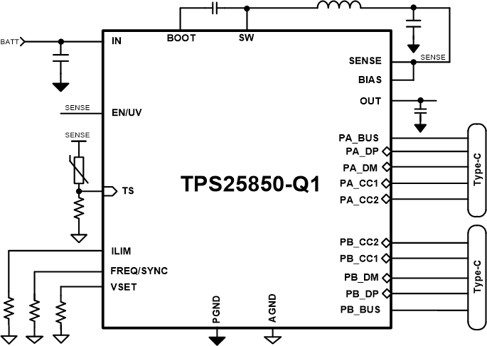
GUID-20201004-CA0I-SDFZ-2BDT-GS0RXQMK2KZZ-low.gifTPS25850-Q1 の概略回路図
GUID-20201005-CA0I-QLHK-PPVQ-KBVDZR1KMZBC-low.gif効率と出力電流との関係