JAJSKP2E august 2020 – august 2023 TPS37-Q1
PRODUCTION DATA
- 1
- 1 特長
- 2 アプリケーション
- 3 概要
- 4 Revision History
- 5 Device Comparison
- 6 Pin Configuration and Functions
- 7 Specifications
- 8 Detailed Description
- 9 Device Functional Modes
- 10Application and Implementation
- 11Device and Documentation Support
パッケージ・オプション
メカニカル・データ(パッケージ|ピン)
サーマルパッド・メカニカル・データ
- DSK|10
発注情報
8.3.2.1 SENSE Hysteresis
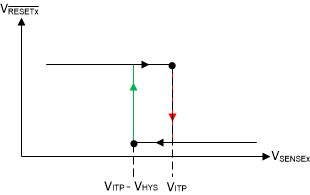
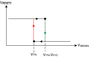
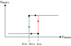
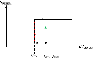
Built-in hysteresis to avoid erroneous output reset release. The hysteresis is opposite to the threshold voltage; for overvoltage options the hysteresis is subtracted from the positive threshold (VITP), for undervoltage options hysteresis is added to the negative threshold (VITN).
 Figure 8-4 Hysteresis (Overvoltage
Active-Low)
 Figure 8-6 Hysteresis (Undervoltage
Active-High)
 Figure 8-5 Hysteresis (Overvoltage
Active-High)
 Figure 8-7 Hysteresis (Undervoltage
Active-Low)
Figure 8-7 Hysteresis (Undervoltage
Active-Low)| TARGET | DEVICE ACTUAL HYSTERESIS OPTION | ||
|---|---|---|---|
| DETECT THRESHOLD | TOPOLOGY | RELEASE VOLTAGE (V) | |
| 18.0 V | Overvoltage | 17.5 V | -3% |
| 18.0 V | Overvoltage | 16.0 V | -11% |
| 17.0 V | Overvoltage | 16.5 V | -3% |
| 16.0 V | Overvoltage | 15.0 V | -6% |
| 15.0 V | Overvoltage | 14.0 V | -7% |
| 6.0 V | Undervoltage | 6.5 V | 0.5 V |
| 5.5 V | Undervoltage | 6 V | 0.5 V |
| 8 V | Undervoltage | 9 V | 1 V |
| 5 V | Undervoltage | 7.5 V | 2.5 V |
Table 8-1 shows a sample of hysteresis and voltage options for the TPS37-Q1. For threshold voltages ranging from 2.7 V to 8 V, one option is to select a fixed hysteresis value ranging from 0.5 V to 2.5 V in increments of 0.5 V. Additionally, a second option can be selected where the hysteresis value is a percentage of the threshold voltage. The percentage of voltage hysteresis ranges from 2% to 13%.
Knowing the amount of hysteresis voltage,
the release voltage for the undervoltage (UV) channel is
(VITN(UV) + VHYS) and for the overvoltage (OV) channel is
(VITP(OV) - VHYS). For a visual understanding of the UV and OV
release voltage, see SENSEx Undervoltage (UV) Timing Diagram and SENSEx Overvoltage (OV)
Timing Diagram. The accuracy of the release voltage, or stated in the Section 7.5 as Hysteresis Accuracy is ±1.5%. Expanding what is shown in Table 8-1, below are a few voltage hysteresis examples that include the hysteresis accuracy:
Undervoltage (UV) Channel
VITN = 0.8 V
Voltage Hysteresis (VHYS) = 5% = 40 mV
Hysteresis Accuracy = ±1.5% = 39.4 mV or 40.6 mV
Release Voltage = VITN + VHYS = 839.4 mV to 840.6 mV
Overvoltage (OV) Channel
VITP = 8 V
Voltage Hysteresis (VHYS) = 2 V
Hysteresis Accuracy = ±1.5% = 1.97 V or 2.03 V
Release Voltage = VITP - VHYS = 5.97 V to 6.03 V