-
TPS40200 Wide Input Range Non-Synchronous Voltage Mode Controller
- 1 Features
- 2 Applications
- 3 Description
- 4 Revision History
- 5 Pin Configuration and Functions
- 6 Specifications
- 7 Detailed Description
-
8 Application and Implementation
- 8.1 Application Information
- 8.2
Typical Application
- 8.2.1
Buck Regulator, 8 V to 12 V Input, 3.3 V to 5.0 V at 2.5-A Output
- 8.2.1.1 Design Requirements
- 8.2.1.2
Detailed Design Procedure
- 8.2.1.2.1 FET Selection Criteria
- 8.2.1.2.2 Rectifier Selection Criteria
- 8.2.1.2.3 Inductor Selection Criteria
- 8.2.1.2.4 Output Capacitance
- 8.2.1.2.5 Switching Frequency
- 8.2.1.2.6 Calculating the Overcurrent Threshold Level
- 8.2.1.2.7 Soft-Start Capacitor
- 8.2.1.2.8 Frequency Compensation
- 8.2.1.2.9 Printed Circuit Board Plots
- 8.2.1.3 Application Curves
- 8.2.2 18 V - 50 V Input, 16 V at 1-A Output
- 8.2.3 Wide Input Voltage Led Constant Current Driver
- 8.2.1
Buck Regulator, 8 V to 12 V Input, 3.3 V to 5.0 V at 2.5-A Output
- 9 Power Supply Recommendations
- 10Layout
- 11Device and Documentation Support
- 12Mechanical, Packaging, and Orderable Information
- IMPORTANT NOTICE
パッケージ・オプション
デバイスごとのパッケージ図は、PDF版データシートをご参照ください。
メカニカル・データ(パッケージ|ピン)
- D|8
- DRB|8
サーマルパッド・メカニカル・データ
- DRB|8
発注情報
TPS40200 Wide Input Range Non-Synchronous Voltage Mode Controller
1 Features
- Input Voltage Range 4.5 V to 52 V
- Output Voltage (700 mV to 90% VIN)
- 200-mA Internal P-channel FET Driver
- Voltage Feed-Forward Compensation
- Undervoltage Lockout
- Programmable Fixed-Frequency (between 35 kHz and 500 kHz) Operation
- Programmable Short-Circuit Protection
- Hiccup Overcurrent Fault Recovery
- Programmable Closed-Loop Soft-Start
- 700 mV 1% Reference Voltage
- External Synchronization
- Small 8-Pin SOIC (D) and VSON (DRB) Packages
2 Applications
- Industrial Control
- Distributed Power Systems
- DSL/Cable Modems
- Scanners
- Telecom
3 Description
The TPS40200 is a flexible, non-synchronous controller with a built-in 200-mA driver for P-channel FETs. The circuit operates with inputs up to 52 V with a power-saving feature that turns off driver current once the external FET has been fully turned on. This feature extends the flexibility of the device, allowing it to operate with an input voltage up to 52 V without dissipating excessive power. The circuit operates with voltage-mode feedback and has feed-forward input voltage compensation that responds instantly to input voltage change. The integral 700-mV reference is trimmed to 2%, providing the means to accurately control low voltages. The TPS40200 is available in an 8-pin SOIC and an 8-pin VSON package and supports many of the features of more complex controllers. Clock frequency, soft-start, and overcurrent limits are each easily programmed by a single, external component. The part has undervoltage lockout, and can be easily synchronized to other controllers or a system clock to satisfy sequencing and/or noise-reduction requirements.
Device Information(1)
| PART NUMBER | PACKAGE | BODY SIZE (NOM) |
|---|---|---|
| TPS40200 | VSON (8) | 3.00 mm x 3.00 mm |
| SOIC (8) | 4.90 mm x 3.90 mm |
- For all available packages, see the orderable addendum at the end of the datasheet.
Simplified Schematic

Efficiency vs Output Current

4 Revision History
Changes from F Revision (September 2014) to G Revision
- Changed Added Handling Rating table, Feature Description section, Device Functional Modes, Application and Implementation section, Power Supply Recommendations section, Layout section, Device and Documentation Support section, and Mechanical, Packaging, and Orderable Information section. Go
5 Pin Configuration and Functions


Pin Functions
| PIN | I/O | DESCRIPTION | |
|---|---|---|---|
| NAME | NO. | ||
| COMP | 3 | O | Error amplifier output. Connect control loop compensation network from COMP to FB. |
| FB | 4 | I | Error amplifier inverting input. Connect feedback resistor network center tap to this pin. |
| GND | 5 | Device ground. | |
| GDRV | 6 | O | Driver output for external P-channel MOSFET |
| ISNS | 7 | I | Current-sense comparator input. Connect a current sense resistor between ISNS and VDD in order to set desired overcurrent threshold. |
| RC | 1 | I | Switching frequency setting RC network. Connect a capacitor from the RC pin to the GND pin and connect a resistor from the VDD pin to the RC pin. The device may be synchronized to an external clock by connecting an open drain output to this pin and pulling it to GND. For mor info on pulse width for synchronization, please refer to the Synchronizing the Oscillator section. |
| SS | 2 | I | Soft-start programming pin. Connect capacitor from SS to GND to program soft start time. Pulling this pin below 150 mV causes the output switching to stop, placing the device in a shutdown state. The pin also functions as a restart timer for overcurrent events. |
| VDD | 8 | I | System input voltage. Connect local bypass capacitor from VDD to GND. |
6 Specifications
6.1 Absolute Maximum Ratings
over operating free-air temperature range (unless otherwise noted) (1)| MIN | MAX | UNIT | |||
|---|---|---|---|---|---|
| Input voltage range | VDD , ISNS | –0.3 | 52 | V | |
| RC, FB | –0.3 | 5.5 | |||
| SS | –0.3 | 9.0 | |||
| Output voltage range | COMP | –0.3 | 9.0 | V | |
| GDRV | VIN –10 | VIN | |||
| TJ | Operating Junction Temperature | –40 | 125 | °C | |
| Lead temperature 1,6 mm (1/16 inch) from case for 10 seconds | 260 | ||||
6.2 Handling Ratings
| MIN | MAX | UNIT | |||
|---|---|---|---|---|---|
| Tstg | Storage temperature range | –55 | 150 | °C | |
| V(ESD) | Electrostatic discharge | Human body model (HBM), per ANSI/ESDA/JEDEC JS-001, all pins(1) | –1500 | 1500 | V |
| Charged device model (CDM), per JEDEC specification JESD22-C101, all pins(2) | –1500 | 1500 | |||
6.3 Recommended Operating Conditions
over operating free-air temperature range (unless otherwise noted)| MIN | MAX | UNIT | ||
|---|---|---|---|---|
| VDD | Input voltage | 4.5 | 52 | V |
| TJ | Operating temperature range | –40 | 125 | °C |
6.4 Thermal Information
| THERMAL METRIC(1) | D | DRB | UNIT | |
|---|---|---|---|---|
| SOIC | VSON | |||
| (8 PINS) | (8 PINS) | |||
| RθJA | Junction-to-ambient thermal resistance | 109.6 | 44.2 | °C/W |
| RθJC(top) | Junction-to-case (top) thermal resistance | 54.0 | 53.6 | |
| RθJB | Junction-to-board thermal resistance | 49.6 | 19.8 | |
| ψJT | Junction-to-top characterization parameter | 11.2 | 1.1 | |
| ψJB | Junction-to-board characterization parameter | 49.1 | 19.9 | |
| RθJC(bot) | Junction-to-case (bottom) thermal resistance | N/A | 7.9 | |
6.5 Electrical Characteristics
–40°C < TA = TJ < 85°C, VDD = 12 V, fOSC = 100 kHz (unless otherwise noted)| PARAMETER | TEST CONDITIONS | MIN | TYP | MAX | UNIT | ||
|---|---|---|---|---|---|---|---|
| VOLTAGE REFERENCE | |||||||
| VFB | Feedback voltage | COMP = FB, TA = 25°C | 689 | 696 | 702 | mV | |
| 4.5 < VDD < 52 | TA = 25°C | 686 | 696 | 703 | |||
| –40°C < TA < 85°C | 679 | 696 | 708 | ||||
| –40°C < TA < 125°C | 679 | 696 | 710 | ||||
| GATE DRIVER | |||||||
| Isrc | Gate driver pull-up current | 125 | 300 | mA | |||
| Isnk | Gate driver pull-down current | 200 | 300 | mA | |||
| VGATE | Gate driver output voltage | VGATE = (VDD – VGDRV), for 12 < VDD < 52 | 6 | 8 | 10 | V | |
| QUIESCENT CURRENT | |||||||
| Iqq | Device quiescent current | fOSC = 300 kHz, Driver not switching, 4.5 < VDD < 52 | 1.5 | 3.0 | mA | ||
| UNDERVOLTAGE LOCKOUT (UVLO) | |||||||
| VUVLO(on) | Turn-on threshold | –40°C < TA < 125°C | 3.8 | 4.25 | 4.5 | V | |
| VUVLO(off) | Turn-off threshold | 4.05 | |||||
| VUVLO(HYST) | Hysteresis | 110 | 200 | 275 | mV | ||
| SOFT-START | |||||||
| RSS(chg) | Internal soft-start pull-up resistance | 65 | 105 | 170 | kΩ | ||
| RSS(dchg) | Internal soft-start pull-down resistance | 190 | 305 | 485 | |||
| VSSRST | Soft-start reset threshold | 100 | 150 | 200 | mV | ||
| OVERCURRENT PROTECTION | |||||||
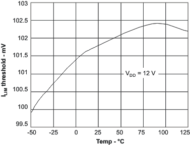
| VILIM | Overcurrent threshold | 4.5 < VDD < 52 | 0°C < TA < 125°C | 65 | 100 | 140 | mV |
| –40°C < TA < 125°C | 55 | 100 | 140 | ||||
| OCDF | Overcurrent duty cycle(1) | 2% | |||||
| VILIM(rst) | Overcurrent reset threshold | 100 | 150 | 200 | mV | ||
| OSCILLATOR | |||||||
| fOSC | Oscillator frequency range(1) | 35 | 500 | kHz | |||
| Oscillator frequency | RRC = 200 kΩ, CRC = 470 pF | 85 | 100 | 115 | |||
| RRC = 68.1 kΩ, CRC = 470 pF | 255 | 300 | 345 | ||||
| Frequency line regulation | 12 V < VDD < 52 V | -9% | 0% | ||||
| 4.5 V < VDD < 12 V | –20% | 0% | |||||
| VRMP | Ramp amplitude | 4.5 V < VDD < 52 V | VDD÷10 | V | |||
| PULSE WIDTH MODULATOR | |||||||
| tMIN | Minimum controllable pulse width(2) | VDD = 12 V | 200 | 400 | ns | ||
| VDD = 30 V | 100 | 200 | |||||
| DMAX | Maximum duty cycle | fosc = 100 kHz, CL = 470 pF | 93% | 95% | |||
| fosc = 300 kHz, CL = 470 pF | 90% | 93% | |||||
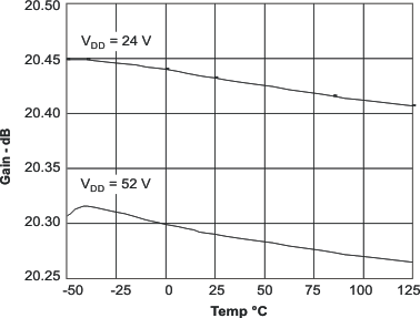
| KPWM | Modulator and power stage DC gain | 8 | 10 | 12 | V/V | ||
| ERROR AMPLIFIER | |||||||
| IIB | Input bias current | 100 | 250 | nA | |||
| AOL | Open loop gain(1) | 60 | 80 | dB | |||
| GBWP | Unity gain bandwidth(1) | 1.5 | 3 | MHz | |||
| ICOMP(src) | Output source current | VFB = 0.6 V, COMP = 1 V | 100 | 250 | μA | ||
| ICOMP(snk) | Output sink current | VFB = 1.2 V, COMP = 1 V | 1.0 | 2.5 | mA | ||
6.6 Typical Characteristics


