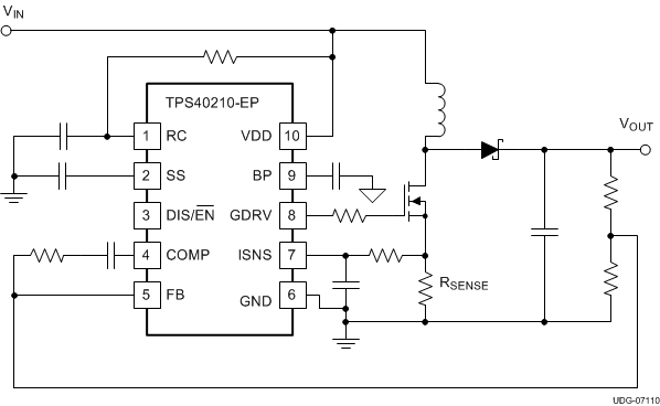
The TPS40210-EP is a wide-input voltage (4.5 to 52 V), nonsynchronous boost controller. The device is suitable for topologies which require a grounded source N-channel FET including boost, flyback, SEPIC, and various LED driver applications. The device features include programmable soft-start, overcurrent protection with automatic retry, and programmable oscillator frequency. Current mode control provides improved transient response and simplified loop compensation.
PART NUMBER | PACKAGE | BODY SIZE (NOM) |
---|---|---|
TPS40210-EP | VSON (10) | 3.05 mm × 4.98 mm |
DATE | REVISION | NOTES |
---|---|---|
November 2015 | * | Initial release. |
PIN | I/O | DESCRIPTION | |
---|---|---|---|
NAME | NO. | ||
BP | 9 | O | Regulator output pin. Connect a 1.0-μF bypass capacitor from this pin to GND. |
COMP | 4 | O | Error amplifier output. Connect control loop compensation network between COMP pin and FB pin. |
DIS/EN | 3 | I | Disable pin. Pulling this pin high, places the part into a shutdown mode. Shutdown mode is characterized by a very low quiescent current. While in shutdown mode, the functionality of all blocks is disabled and the BP regulator is shut down. This pin has an internal 1 MΩ pull-down resistor to GND. Leaving this pin unconnected enables the device. |
FB | 5 | I | Error amplifier inverting input. Connect a voltage divider from the output to this pin to set output voltage. Compensation network is connected between this pin and COMP. |
GDRV | 8 | O | Connect the gate of the power N channel MOSFET to this pin. |
GND | 6 | — | Device ground. |
ISNS | 7 | I | Current sense pin. Connect an external current sensing resistor between this pin and GND. The voltage on this pin is used to provide current feedback in the control loop and detect an overcurrent condition. An overcurrent condition is declared when ISNS pin voltage exceeds the overcurrent threshold voltage, 150 mV typical. |
RC | 1 | I | Switching frequency setting pin. Connect a resistor from RC pin to VDD of the IC power supply and a capacitor from RC to GND. |
SS | 2 | I | Soft-start time programming pin. Connect capacitor from SS pin to GND to program converter soft-start time. This pin also functions as a timeout timer when the power supply is in an overcurrent condition. |
VDD | 10 | I | System input voltage. Connect a local bypass capacitor from this pin to GND. Depending on the amount of required slope compensation, this pin can be connected to the converter output. See Application Information for additional details. |
MIN | MAX | UNIT | |||
---|---|---|---|---|---|
Input voltage | VDD | –0.3 | 52 | V | |
RC, SS, FB, DIS/EN | –0.3 | 10 | |||
ISNS | –0.3 | 8 | |||
Output voltage | COMP, BP, GDRV | –0.3 | 9 | ||
TJ | Operating junction temperature | –55 | 150 | °C | |
Tstg | Storage temperature | –55 | 150 | °C |
VALUE | UNIT | |||
---|---|---|---|---|
V(ESD) | Electrostatic discharge | Human-body model (HBM), per ANSI/ESDA/JEDEC JS-001(1) | ±1500 | V |
Charged-device model (CDM), per JEDEC specification JESD22-C101(2) | ±1500 |
MIN | MAX | UNIT | ||
---|---|---|---|---|
VDD | Input voltage | 4.5 | 52 | V |
TJ | Operating junction temperature | –55 | 125 | °C |
THERMAL METRIC(1) | TPS40210-EP | UNIT | |
---|---|---|---|
DRC (VSON) | |||
10 PINS | |||
RθJA | Junction-to-ambient thermal resistance | 67.2 | °C/W |
RθJC(top) | Junction-to-case (top) thermal resistance | 50.5 | °C/W |
RθJB | Junction-to-board thermal resistance | 41.0 | °C/W |
ψJT | Junction-to-top characterization parameter | 2.4 | °C/W |
ψJB | Junction-to-board characterization parameter | 40.7 | °C/W |
RθJC(bot) | Junction-to-case (bottom) thermal resistance | 15.6 | °C/W |
PARAMETER | TEST CONDITIONS | MIN | TYP | MAX | UNIT | |||
---|---|---|---|---|---|---|---|---|
VOLTAGE REFERENCE | ||||||||
VFB | Feedback voltage range | COMP = FB, 4.5 ≤ VDD ≤ 52 V, TJ = 25°C | 693 | 700 | 707 | mV | ||
COMP = FB, 4.5 ≤ VDD ≤ 52 V, –55°C ≤ TJ ≤ 125°C | 686 | 700 | 714 | |||||
INPUT SUPPLY | ||||||||
VDD | Input voltage range | 4.5 | 52 | V | ||||
IDD | Operating current | 4.5 ≤ VDD ≤ 52 V, no switching, VDIS < 0.8 | 1.5 | 2.5 | mA | |||
2.5 ≤ VDIS ≤ 7 V | 10 | 20 | μA | |||||
VDD < VUVLO(on), VDIS < 0.8 | 530 | μA | ||||||
UNDERVOLTAGE LOCKOUT | ||||||||
VUVLO(on) | Turn on threshold voltage | 4.00 | 4.25 | 4.50 | V | |||
VUVLO(hyst) | UVLO hysteresis | 140 | 195 | 240 | mV | |||
OSCILLATOR | ||||||||
ƒOSC | Oscillator frequency range(1) | 35 | 1000 | kHz | ||||
Oscillator frequency | RRC = 182 kΩ, CRC = 330 pF | 260 | 300 | 340 | ||||
Frequency line regulation | 4.5 ≤ VDD ≤ 52 V | -20% | 7% | |||||
VSLP | Slope compensation ramp | 520 | 620 | 720 | mV | |||
PWM | ||||||||
tON(min) | Minimum pulse width | VDD = 12 V(1) | 275 | 400 | ns | |||
VDD = 30 V | 90 | 200 | ||||||
tOFF(min) | Minimum off time | 170 | 200 | |||||
VVLY | Valley voltage | 1.2 | V | |||||
SOFT-START | ||||||||
VSS(ofst) | Offset voltage from SS pin to error amplifier input | 700 | mV | |||||
RSS(chg) | Soft-start charge resistance | 320 | 430 | 620 | kΩ | |||
RSS(dchg) | Soft-start discharge resistance | 840 | 1200 | 1600 | ||||
ERROR AMPLIFIER | ||||||||
GBWP | Unity gain bandwidth product(1) | 1.5 | 3.0 | MHz | ||||
AOL | Open loop gain(1) | 60 | 80 | dB | ||||
IIB(FB) | Input bias current (current out of FB pin) | 100 | 300 | nA | ||||
ICOMP(src) | Output source current | VFB = 0.6 V, VCOMP = 1 V | 100 | 250 | μA | |||
ICOMP(snk) | Output sink current | VFB = 1.2 V, VCOMP = 1 V | 1.2 | 2.5 | mA | |||
OVERCURRENT PROTECTION | ||||||||
VISNS(oc) | Overcurrent detection threshold (at ISNS pin) | 4.5 ≤ VDD < 52 V, –55°C ≤ TJ ≤ 125°C | 120 | 150 | 180 | mV | ||
DOC | Overcurrent duty cycle(1) | 2% | ||||||
VSS(rst) | Overcurrent reset threshold voltage (at SS pin) | 100 | 150 | 350 | mV | |||
TBLNK | Leading edge blanking(1) | 75 | ns | |||||
CURRENT SENSE AMPLIFIER | ||||||||
ACS | Current sense amplifier gain | 4..2 | 5.6 | 7.4 | V/V | |||
IB(ISNS) | Input bias current | 1 | 3 | μA | ||||
DRIVER | ||||||||
IGDRV(src) | Gate driver source current | VGDRV = 4 V, TJ = 25°C | 375 | 400 | mA | |||
IGDRV(snk) | Gate driver sink current | VGDRV = 4 V, TJ = 25°C | 330 | 400 | ||||
LINEAR REGULATOR | ||||||||
VBP | Bypass voltage output | 0 mA < IBP < 15 mA | 7 | 8 | 9 | V | ||
DISABLE/ENABLE | ||||||||
VDIS(en) | Turn-on voltage | 0.7 | 1.3 | V | ||||
VDIS(hys) | Hysteresis voltage | 25 | 130 | 220 | mV | |||
RDIS | DIS pin pulldown resistance | 0.7 | 1.1 | 1.6 | MΩ |