JAJSDD3B June 2017 – January 2019 TPS53681
PRODUCTION DATA.
- 1 特長
- 2 アプリケーション
- 3 概要
- 4 改訂履歴
- 5 Pin Configuration and Functions
-
6 Specifications
- 6.1 Absolute Maximum Ratings
- 6.2 ESD Ratings
- 6.3 Recommended Operating Conditions
- 6.4 Thermal Information
- 6.5 Supply: Currents, UVLO, and Power-On Reset
- 6.6 References: DAC and VREF
- 6.7 Voltage Sense: AVSP and BVSP, AVSN and BVSN
- 6.8 Telemetry
- 6.9 Input Current Sensing
- 6.10 Programmable Loadline Settings
- 6.11 Current Sense and Calibration
- 6.12 Logic Interface Pins: AVR_EN, AVR_RDY, BVR_EN, BVR_RDY, RESET, VR_FAULT, VR_HOT
- 6.13 I/O Timing
- 6.14 PMBus Address Setting
- 6.15 Overcurrent Limit Thresholds
- 6.16 Switching Frequency
- 6.17 Slew Rate Settings
- 6.18 Ramp Selections
- 6.19 Dynamic Integration and Undershoot Reduction
- 6.20 Boot Voltage and TMAX Settings
- 6.21 Protections: OVP and UVP
- 6.22 Protections: ATSEN and BTSEN Pin Voltage Levels and Fault
- 6.23 PWM: I/O Voltage and Current
- 6.24 Dynamic Phase Add and Drop
- 6.25 Typical Characteristics
-
7 Detailed Description
- 7.1 Overview
- 7.2 Functional Block Diagram
- 7.3 Feature Description
- 7.4 Device Functional Modes
- 7.5
Programming
- 7.5.1 PMBus Connections
- 7.5.2 PMBus Address Selection
- 7.5.3 Supported Commands
- 7.5.4 Commonly Used PMBus Commands
- 7.5.5 Voltage, Current, Power, and Temperature Readings
- 7.5.6 Input Current Sense and Calibration
- 7.5.7 Output Current Sense and Calibration
- 7.5.8 Output Voltage Margin Testing
- 7.5.9 Loop Compensation
- 7.5.10 Converter Protection and Response
- 7.5.11 Output Overvoltage Protection and Response
- 7.5.12 Maximum Allowed Output Voltage Setting
- 7.5.13 Output Undervoltage Protection and Response
- 7.5.14 Minimum Allowed Output Voltage Setting
- 7.5.15 Output Overcurrent Protection and Response
- 7.5.16 Input Under-Voltage Lockout (UVLO)
- 7.5.17 Input Over-Voltage Protection and Response
- 7.5.18 Input Undervoltage Protection and Response
- 7.5.19 Input Overcurrent Protection and Response
- 7.5.20 Over-Temperature Protection and Response
- 7.5.21 Dynamic Phase Shedding (DPS)
- 7.5.22 NVM Programming
- 7.5.23 NVM Security
- 7.5.24 Black Box Recording
- 7.5.25 Board Identification and Inventory Tracking
- 7.5.26 Status Reporting
-
8 Applications, Implementation, and Layout
- 8.1 Application Information
- 8.2 Typical Application
- 9 Power Supply Recommendations
- 10Layout
- 11デバイスおよびドキュメントのサポート
- 12メカニカル、パッケージ、および注文情報
パッケージ・オプション
メカニカル・データ(パッケージ|ピン)
- RSB|40
サーマルパッド・メカニカル・データ
- RSB|40
発注情報
7.3.1 Phase Interleaving and PWM Operation
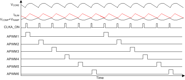
As shown in the Overview section, in 8-phase continuous conduction mode, the device operates as described in Figure 5.
 Figure 5. D-CAP+ Mode Basic Waveforms
 Starting with the condition that the high-side FETs are off and the low-side FETs are on, the summed current feedback (VISUM) is higher than the summed error amplifier output (VCOMP) and the internal ramp signal (VRAMP). ISUM falls until it hits VCOMP+VRAMP, which contains a component of the output ripple voltage. The PWM comparator senses where the two waveforms cross and triggers the on-time generator. This generates the internal CLKA_ON signal. Each CLKA_ON signal corresponds to one switching ON pulse for one phase.
In case of single-phase operation, every CLKA_ON signal generates a switching pulse on the same phase. Also, VISUM corresponds to just a single-phase inductor current.
In case of multi-phase operation, the CLKA_ON signal gets distributed to each of the phases in a cycle. This approach of using the summed inductor current and cyclically distributing the ON pulses to each phase automatically gives the required interleaving of 360 / n, where n is the number of phases.