JAJSCB6B May 2016 – April 2021 TPS54302
PRODUCTION DATA
- 1 特長
- 2 アプリケーション
- 3 概要
- 4 Revision History
- 5 Pin Configuration and Functions
- 6 Specifications
-
7 Detailed Description
- 7.1 Overview
- 7.2 Functional Block Diagram
- 7.3
Feature Description
- 7.3.1 Fixed-Frequency PWM Control
- 7.3.2 Pulse Skip Mode
- 7.3.3 Error Amplifier
- 7.3.4 Slope Compensation and Output Current
- 7.3.5 Enable and Adjusting Undervoltage Lockout
- 7.3.6 Safe Startup into Pre-Biased Outputs
- 7.3.7 Voltage Reference
- 7.3.8 Adjusting Output Voltage
- 7.3.9 Internal Soft-Start
- 7.3.10 Bootstrap Voltage (BOOT)
- 7.3.11 Overcurrent Protection
- 7.3.12 Spread Spectrum
- 7.3.13 Output Overvoltage Protection (OVP)
- 7.3.14 Thermal Shutdown
- 7.4 Device Functional Modes
- 8 Application and Implementation
- 9 Power Supply Recommendations
- 10Layout
- 11Device and Documentation Support
- 12Mechanical, Packaging, and Orderable Information
パッケージ・オプション
デバイスごとのパッケージ図は、PDF版データシートをご参照ください。
メカニカル・データ(パッケージ|ピン)
- DDC|6
サーマルパッド・メカニカル・データ
発注情報
3 概要
TPS54302 は入力電圧範囲が 4.5V~28V で、3A の同期整流降圧型コンバータです。このデバイスには 2 つの内蔵スイッチング FET、内部的なループ補償、および 5ms の内部ソフトスタートが搭載されているため、部品数を減らすことができます。
TPS54302 には MOSFET が内蔵され、SOT-23 パッケージを採用しているため、高い電力密度を実現し、PCB 上でわずかな面積しか占有しません。
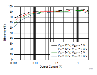
高度な Eco-mode の実装により、軽負荷時の効率が最大化され、電力損失が低減されています。
TPS54302 デバイスでは、EMI 低減の目的で周波数スペクトラム拡散動作を採用しています。
両方のハイサイド MOSFET でサイクル単位の電流制限を行い、過負荷の状況でコンバータを保護します。また、ローサイド MOSFET の電流制限を自由に設定でき、電流暴走を防止することで、さらに保護が強化されています。プリセット時間を上回る長さで過電流状態が続いた場合、ヒカップ・モード保護機能をトリガします。
製品情報
| 部品番号 | パッケージ(1) | 本体サイズ (公称) |
|---|---|---|
| TPS54302 | SOT-23-THIN (6) | 1.60mm × 2.90mm |
(1) 利用可能なすべてのパッケージについては、このデータシートの末尾にある注文情報を参照してください。
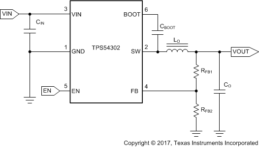
 概略回路図
概略回路図 効率と出力電流との関係