JAJSKM9B July 2020 – November 2020 TPS54JB20
PRODUCTION DATA
- 1 特長
- 2 アプリケーション
- 3 概要
- 4 Revision History
- 5 Pin Configuration and Functions
- 6 Specifications
-
7 Detailed Description
- 7.1 Overview
- 7.2 Functional Block Diagram
- 7.3
Feature Description
- 7.3.1 Internal VCC LDO And Using External Bias On VCC Pin
- 7.3.2 Enable
- 7.3.3 Output Voltage Setting
- 7.3.4 Internal Fixed Soft Start and External Adjustable Soft Start
- 7.3.5 External REFIN For Output Voltage Tracking
- 7.3.6 Frequency and Operation Mode Selection
- 7.3.7 D-CAP3 Control
- 7.3.8 Low-side FET Zero-Crossing
- 7.3.9 Current Sense and Positive Overcurrent Protection
- 7.3.10 Low-side FET Negative Current Limit
- 7.3.11 Power Good
- 7.3.12 Overvoltage and Undervoltage Protection
- 7.3.13 Out-Of-Bounds (OOB) Operation
- 7.3.14 Output Voltage Discharge
- 7.3.15 UVLO Protection
- 7.3.16 Thermal Shutdown
- 7.4 Device Functional Modes
-
8 Application and Implementation
- 8.1 Application Information
- 8.2
Typical Application
- 8.2.1 Design Requirements
- 8.2.2
Detailed Design Procedure
- 8.2.2.1 Output Voltage Setting Point
- 8.2.2.2 Choose the Switching Frequency and the Operation Mode
- 8.2.2.3 Choose the Inductor
- 8.2.2.4 Set the Current Limit (TRIP)
- 8.2.2.5 Choose the Output Capacitor
- 8.2.2.6 Choose the Input Capacitors (CIN)
- 8.2.2.7 Soft Start Capacitor (SS/REFIN Pin)
- 8.2.2.8 EN Pin Resistor Divider
- 8.2.2.9 VCC Bypass Capacitor
- 8.2.2.10 BOOT Capacitor
- 8.2.2.11 Series BOOT Resistor and RC Snubber
- 8.2.2.12 PGOOD Pullup Resistor
- 8.2.3 Application Curves
- 9 Power Supply Recommendations
- 10Layout
- 11Device and Documentation Support
- 12Mechanical, Packaging, and Orderable Information
3 概要
TPS54JB20 デバイスは、適応型オン時間 D-CAP3 制御モードを備えた小型で高効率の同期整流式降圧コンバータです。外部補償が不要のため、本デバイスは使いやすく、外付け部品をほとんど必要としません。本デバイスは、スペースに制約のあるデータ・センター・アプリケーションによく適しています。
TPS54JB20 デバイスは、差動リモート・センス、高性能の内蔵 MOSFET、動作時接合部温度の全範囲にわたって高精度 (±1%) の 0.9V 基準電圧を備えています。本デバイスは、高速な負荷過渡応答、精密な負荷レギュレーションとライン・レギュレーション、スキップ・モードまたは FCCM 動作、プログラム可能なソフトスタートを特長としています。
TPS54JB20 デバイスは鉛フリー・デバイスです。RoHS に完全準拠しています (適用除外なし)。
製品情報
| 部品番号(1) | パッケージ | 本体サイズ (公称) |
|---|---|---|
| TPS54JB20 | VQFN-HR (21) | 4.00mm × 3.00mm |
(1) 利用可能なすべてのパッケージについては、このデータシートの末尾にある注文情報を参照してください。
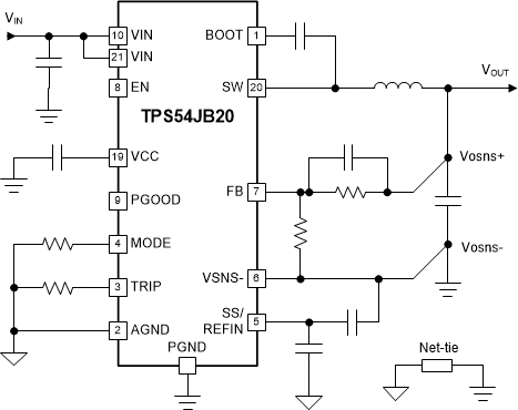
 概略回路図
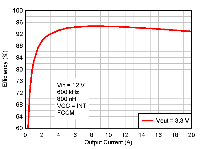
概略回路図 効率のグラフ