SLVSC20E January 2015 – October 2016 TPS62134A , TPS62134B , TPS62134C , TPS62134D
PRODUCTION DATA.
- 1 Features
- 2 Applications
- 3 Description
- 4 Revision History
- 5 Device Comparison Table
- 6 Pin Configuration and Functions
- 7 Specifications
-
8 Detailed Description
- 8.1 Overview
- 8.2 Functional Block Diagram
- 8.3
Feature Description
- 8.3.1 Enable and Shutdown (EN)
- 8.3.2 Undervoltage Lockout (UVLO)
- 8.3.3 Soft-Start (SS) Circuitry
- 8.3.4 Switch Current-Limit and Short Circuit Protection
- 8.3.5 Output Voltage and LPM Logic Selection (VIDx and LPM)
- 8.3.6 Power-Good Output (PG)
- 8.3.7 Single-Ended Remote Sense (FBS)
- 8.3.8 Thermal Shutdown
- 8.4 Device Functional Modes
- 9 Application and Implementation
- 10Power Supply Recommendations
- 11Layout
- 12Device and Documentation Support
- 13Mechanical, Packaging, and Orderable Information
パッケージ・オプション
メカニカル・データ(パッケージ|ピン)
- RGT|16
サーマルパッド・メカニカル・データ
- RGT|16
発注情報
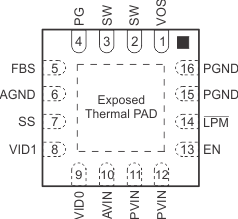
6 Pin Configuration and Functions
RGT Package
16-Pin VQFN With Thermal Pad
Top View
