-
TPS6220x High-Efficiency, SOT23 Step-Down, DC-DC Converter
- 1 Features
- 2 Applications
- 3 Description
- 4 Revision History
- 5 Pin Configuration and Functions
- 6 Specifications
- 7 Detailed Description
- 8 Application and Implementation
- 9 Power Supply Recommendations
- 10Layout
- 11Device and Documentation Support
- 12Mechanical, Packaging, and Orderable Information
- IMPORTANT NOTICE
デバイスごとのパッケージ図は、PDF版データシートをご参照ください。
メカニカル・データ(パッケージ|ピン)
- DBV|5
サーマルパッド・メカニカル・データ
TPS6220x High-Efficiency, SOT23 Step-Down, DC-DC Converter
1 Features
- High-Efficiency Synchronous Step-Down
Converter With up to 95% Efficiency - 2.5-V to 6-V Input Voltage Range
- Adjustable Output Voltage Range From 0.7 V to VI
- Fixed Output Voltage Options Available
- Up to 300-mA Output Current
- 1-MHz Fixed-Frequency PWM Operation
- Highest Efficiency Over Wide Load Current Range Due to Power Save Mode
- 15-µA Typical Quiescent Current
- Soft Start
- 100% Duty Cycle Low-Dropout Operation
- Dynamic Output-Voltage Positioning
- Available in a 5-Pin SOT23 Package
2 Applications
- PDAs and Pocket PCs
- Cellular Phones and Smart Phones
- Low Power DSP Supplies
- Digital Cameras
- Portable Media Players
- Portable Equipment
3 Description
The TPS6220x devices are a family of high-efficiency synchronous step-down converters ideally suited for portable systems powered by 1-cell Li-Ion or 3-cell NiMH/NiCd batteries. The devices are also suitable to operate from a standard 3.3-V or 5-V voltage rail.
With an output voltage range of 6 V down to 0.7 V and up to 300 mA output current, the devices are ideal to power low voltage DSPs and processors used in PDAs, pocket PCs, and smart phones. Under nominal load current, the devices operate with a fixed switching frequency of typically 1 MHz. At light load currents, the part enters the power save mode operation; the switching frequency is reduced and the quiescent current is typically only 15 µA; therefore, it achieves the highest efficiency over the entire load current range. The TPS6220x needs only three small external components. Together with the SOT23 package, a minimum system solution size is achieved. An advanced fast response voltage mode control scheme achieves superior line and load regulation with small ceramic input and output capacitors.
Device Information(1)
| PART NUMBER | PACKAGE | BODY SIZE (NOM) |
|---|---|---|
| TPS6220x | SOT-23 (5) | 2.90 mm × 1.60 mm |
- For all available packages, see the orderable addendum at the end of the data sheet.
Typical Application Schematic

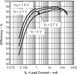
Efficiency vs Load Current

4 Revision History
Changes from E Revision (May 2006) to F Revision
- Added ESD Ratings table, Feature Description section, Device Functional Modes, Application and Implementation section, Power Supply Recommendations section, Layout section, Device and Documentation Support section, and Mechanical, Packaging, and Orderable Information sectionGo
- Changed the format of this data sheet to the new SDA format. No markup for changes. Go
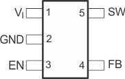
5 Pin Configuration and Functions

Pin Functions
| PIN | I/O | DESCRIPTION | |
|---|---|---|---|
| NAME | NO. | ||
| EN | 3 | I | This is the enable pin of the device. Pulling this pin to ground forces the device into shutdown mode. Pulling this pin to Vin enables the device. This pin must not be left floating and must be terminated. |
| FB | 4 | I | This is the feedback pin of the device. Connect this pin directly to the output if the fixed output voltage version is used. For the adjustable version an external resistor divider is connected to this pin. The internal voltage divider is disabled for the adjustable version. |
| GND | 2 | — | Ground |
| SW | 5 | I/O | Connect the inductor to this pin. This pin is the switch pin and is connected to the internal MOSFET switches. |
| VI | 1 | I | Supply voltage pin |