JAJSLH2 March   2021 TPS62810M , TPS62811M , TPS62812M , TPS62813M

PRODUCTION DATA  

  1. 特長
  2. アプリケーション
  3. 概要
  4. Revision History
  5. Device Comparison Table
  6. Pin Configuration and Functions
  7. Specifications
    1. 7.1 Absolute Maximum Ratings
    2. 7.2 ESD Ratings
    3. 7.3 Recommended Operating Conditions
    4. 7.4 Thermal Information
    5. 7.5 Electrical Characteristics
    6. 7.6 Typical Characteristics
  8. Parameter Measurement Information
    1. 8.1 Schematic
  9. Detailed Description
    1. 9.1 Overview
    2. 9.2 Functional Block Diagram
    3. 9.3 Feature Description
      1. 9.3.1 Precise Enable
      2. 9.3.2 COMP/FSET
      3. 9.3.3 MODE/SYNC
      4. 9.3.4 Spread Spectrum Clocking (SSC)
      5. 9.3.5 Undervoltage Lockout (UVLO)
      6. 9.3.6 Power Good Output (PG)
      7. 9.3.7 Thermal Shutdown
    4. 9.4 Device Functional Modes
      1. 9.4.1 Pulse Width Modulation (PWM) Operation
      2. 9.4.2 Power Save Mode Operation (PWM/PFM)
      3. 9.4.3 100% Duty-Cycle Operation
      4. 9.4.4 Current Limit and Short Circuit Protection
      5. 9.4.5 Foldback Current Limit and Short Circuit Protection
      6. 9.4.6 Output Discharge
      7. 9.4.7 Soft Start/Tracking (SS/TR)
  10. 10Application and Implementation
    1. 10.1 Application Information
      1. 10.1.1 Programming the Output Voltage
      2. 10.1.2 Inductor Selection
      3. 10.1.3 Capacitor Selection
        1. 10.1.3.1 Input Capacitor
        2. 10.1.3.2 Output Capacitor
    2. 10.2 Typical Application
      1. 10.2.1 Design Requirements
      2. 10.2.2 Detailed Design Procedure
      3. 10.2.3 Application Curves
    3. 10.3 System Examples
      1. 10.3.1 Voltage Tracking
      2. 10.3.2 Synchronizing to an External Clock
  11. 11Power Supply Recommendations
  12. 12Layout
    1. 12.1 Layout Guidelines
    2. 12.2 Layout Example
  13. 13Device and Documentation Support
    1. 13.1 Device Support
      1. 13.1.1 Third-Party Products Disclaimer
    2. 13.2 Documentation Support
      1. 13.2.1 Related Documentation
    3. 13.3 Receiving Notification of Documentation Updates
    4. 13.4 サポート・リソース
    5. 13.5 Trademarks
    6. 13.6 静電気放電に関する注意事項
    7. 13.7 用語集
  14. 14Mechanical, Packaging, and Orderable Information

パッケージ・オプション

メカニカル・データ(パッケージ|ピン)
サーマルパッド・メカニカル・データ
発注情報

概要

TPS6281xM はピン互換の 1A、2A、3A、4A の同期整流降圧型 DC/DC コンバータのファミリです。すべてのデバイスは、高い効率と使いやすさを特長としています。本デバイス・ファミリは、ピーク電流モード制御方式に基づいています。低抵抗のスイッチにより、高い周囲温度でも最大 4A の連続出力電流を供給できます。スイッチング周波数は 1.8MHz~4MHz の範囲で外部から変更でき、同じ周波数範囲の外部クロックと同期することもできます。本デバイスは負荷が軽いときに自動的にパワーセーブ・モード (PSM) へ移行するため、負荷範囲全体にわたって高い効率が維持されます。本デバイスは PWM モードで 1% の出力電圧精度を実現するため、出力電圧精度の高い電源の設計に役立ちます。SS/TR ピンを使用すると、起動時間を設定し、または出力電圧が外部電圧源に追従するように構成できるため、各種電源レールを外部からシーケンシングし、起動時の突入電流を制限できます。

TPS6281xM デバイスは、2mm × 3mm のウェッタブル・フランク付き VQFN パッケージで供給されます。

製品情報
部品番号パッケージ(1)本体サイズ (公称)
TPS62810MVQFN2mm × 3mm
TPS62811M
TPS62812M
TPS62813M
利用可能なすべてのパッケージについては、このデータシートの末尾にある注文情報を参照してください。
概略回路図
GUID-464AF12B-EEAF-4C60-885E-100F8931EEF9-low.gif効率と出力電流との関係、
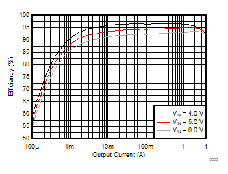
VOUT = 3.3V、PWM/PFM、fS = 2.25MHz