-
TPS629203-Q1 300mA、3V~17V 車載用、 低 IQ 降圧コンバータ
- 1 特長
- 2 アプリケーション
- 3 概要
- 4 Revision History
- 5 Device Comparison Table
- 6 Pin Configuration and Functions
- 7 Specifications
-
8 Detailed Description
- 8.1 Overview
- 8.2 Functional Block Diagram
- 8.3
Feature Description
- 8.3.1 Mode Selection and Device Configuration (MODE/S-CONF Pin)
- 8.3.2 Adjustable VO Operation (External Voltage Divider)
- 8.3.3 Selectable VO Operation (VSET and Internal Voltage Divider)
- 8.3.4 Smart Enable with Precise Threshold
- 8.3.5 Power Good (PG)
- 8.3.6 Output Discharge Function
- 8.3.7 Undervoltage Lockout (UVLO)
- 8.3.8 Current Limit and Short Circuit Protection
- 8.3.9 Thermal Shutdown
- 8.4 Device Functional Modes
- 9 Application and Implementation
- 10Power Supply Recommendations
- 11Layout
- 12Device and Documentation Support
- 13Mechanical, Packaging, and Orderable Information
- 重要なお知らせ
DATA SHEET
TPS629203-Q1 300mA、3V~17V 車載用、 低 IQ 降圧コンバータ
このリソースの元の言語は英語です。 翻訳は概要を便宜的に提供するもので、自動化ツール (機械翻訳) を使用していることがあり、TI では翻訳の正確性および妥当性につきましては一切保証いたしません。 実際の設計などの前には、ti.com で必ず最新の英語版をご参照くださいますようお願いいたします。
1 特長
- 車載アプリケーション用に AEC-Q100 認定済み:
- 動作時の接合部温度範囲:–40℃~150℃
- HBM ESD 分類レベル 2 デバイス
- CDM ESD 分類レベル C4B
- 機能安全対応
- 高効率 DCS-Control トポロジ
- 内部補償
- PWM/PFM のシームレスな切り替え
- 4µA (標準値) の低い静止電流
- 最大 0.3A の出力電流
- RDSON:250mΩ ハイサイド、85mΩ ローサイド
- ±1% の出力電圧精度
- 構成可能な出力電圧:
- VFB 外部分圧器:0.6V~5.5V
- VSET 内部分圧器:
- 0.4V~5.5V の 18 通りの選択肢
- MODE/S-CONF ピンによる優れた柔軟性
- 2.5MHz または 1.0MHz のスイッチング周波数
- 強制 PWM または自動 (PFM) パワー・セーブ・モード (動的モード変更機能付き)
- 出力放電のオン / オフ
- 外部ブートストラップ・コンデンサ不要
- 過電流および過熱保護
- 100% デューティ・サイクル・モード
- 高精度イネーブル入力
- パワー・グッド出力
- TPS629210-Q1、TPS629206-Q1 デバイスとピン互換
- 0.5mm ピッチの 8 ピン SOT-5X3 パッケージ
3 概要
車載用認定済みの TPS6292xx-Q1 デバイス・ファミリは、高効率かつ小型で非常に柔軟性が高く、使いやすい同期整流降圧 DC/DC コンバータです。入力電圧範囲が 3V~17V と広いため、12V、5V、3.3V の電源レールまたはシングル・セル / マルチセル・リチウムイオン・バッテリで動作する各種システムに対応できます。TPS629203-Q1 は、2.5MHz または 1MHz の強制 PWM モードまたは可変周波数 (自動 PFM) モードで動作するように構成できます。自動 PFM モードでは、軽負荷になると自動的にパワー・セーブ・モードに移行して高い効率を維持します。静止電流が 4µA (標準値) と小さいことも、最小の負荷まで高い効率が得られる理由です。TI の自動効率拡張 (AEE) モードを使うと、入力と出力の電圧に基づいてスイッチング周波数が自動的に調整されるため、同じインダクタを使っても動作範囲全域で高い変換効率を維持できます。MODE/S-CONF 入力ピンは、スイッチング周波数の挙動の選択に加えて、外部および内部帰還分圧器の各種組み合わせと出力電圧放電機能のイネーブル / ディセーブルの選択にも使えます。内部帰還構成では、FB/VSET ピンと GND の間に接続する抵抗の値によって 18 種類の出力電圧を選択できます (Table 8-2 を参照)。
デバイス情報
| 部品番号 | パッケージ(1) | 本体サイズ (公称) |
|---|---|---|
| TPS629203-Q1 | SOT-5X3 (8) | 1.60mm × 2.10mm (ピンを含む) |
(1) 利用可能なパッケージについては、このデータシートの末尾にある注文情報を参照してください。
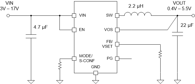
 概略回路図
概略回路図効率と出力電流との関係
VOUT = 3.3V (2.5MHz 自動 PFM/PWM)
VOUT = 3.3V (2.5MHz 自動 PFM/PWM)
4 Revision History
| DATE | REVISION | NOTES |
|---|---|---|
| March 2022 | * | Initial Release |
5 Device Comparison Table
| Device Number | Output Current | Input Voltage | Operating Temperature Range | Switching Frequency | PWM Mode | VO Adjust | |
|---|---|---|---|---|---|---|---|
| TPS629203-Q1 | 0 A–0.3 A | 3 V–17 V | –40°C to 150°C | Selectable 1-MHz or 2.5-MHz options | Selectable auto PWM/PFM or forced PWM | Externally programmable or 18 internal options | |
| TPS629206-Q1 | 0 A–0.6 A | ||||||
| TPS629210-Q1 | 0 A–1 A | ||||||