JAJSM97D June 2021 – August 2022 TPS62932 , TPS62933 , TPS62933F , TPS62933O , TPS62933P
PRODUCTION DATA
- 1 特長
- 2 アプリケーション
- 3 概要
- 4 Revision History
- 5 概要 (続き)
- 6 Device Comparison Table
- 7 Pin Configuration and Functions
- 8 Specifications
-
9 Detailed Description
- 9.1 Overview
- 9.2 Functional Block Diagram
- 9.3
Feature Description
- 9.3.1 Fixed Frequency Peak Current Mode
- 9.3.2 Pulse Frequency Modulation
- 9.3.3 Voltage Reference
- 9.3.4 Output Voltage Setting
- 9.3.5 Switching Frequency Selection
- 9.3.6 Enable and Adjusting Undervoltage Lockout
- 9.3.7 External Soft Start and Prebiased Soft Start
- 9.3.8 Power Good
- 9.3.9 Minimum On Time, Minimum Off Time, and Frequency Foldback
- 9.3.10 Frequency Spread Spectrum
- 9.3.11 Overvoltage Protection
- 9.3.12 Overcurrent and Undervoltage Protection
- 9.3.13 Thermal Shutdown
- 9.4 Device Functional Modes
-
10Application and Implementation
- 10.1 Application Information
- 10.2
Typical Application
- 10.2.1 Design Requirements
- 10.2.2
Detailed Design Procedure
- 10.2.2.1 Custom Design With WEBENCH® Tools
- 10.2.2.2 Output Voltage Resistors Selection
- 10.2.2.3 Choosing Switching Frequency
- 10.2.2.4 Soft-Start Capacitor Selection
- 10.2.2.5 Bootstrap Capacitor Selection
- 10.2.2.6 Undervoltage Lockout Setpoint
- 10.2.2.7 Output Inductor Selection
- 10.2.2.8 Output Capacitor Selection
- 10.2.2.9 Input Capacitor Selection
- 10.2.2.10 Feedforward Capacitor CFF Selection
- 10.2.2.11 Maximum Ambient Temperature
- 10.2.3 Application Curves
- 10.3 What to Do and What Not to Do
- 11Power Supply Recommendations
- 12Layout
- 13Device and Documentation Support
- 14Mechanical, Packaging, and Orderable Information
3 概要
TPS6293x は、3.8V~30V の広い入力電圧範囲を備えた、高効率で使いやすい同期整流降圧コンバータであり、最大 2A (TPS62932) および 3A (TPS62933 および TPS62933x) の連続出力電流と 0.8V~22V の出力電圧をサポートしています。
このデバイスは、固定周波数ピーク電流制御モードを採用して、高速な過渡応答と優れたラインおよび負荷レギュレーションを実現しています。最適化されたループ補償機能を内蔵しているため、外付けの補償部品は不要です。
TPS62932、TPS62933、TPS62933P は、パルス周波数変調で動作し、軽負荷時に高い効率を実現します。TPS62933F は、強制連続電流変調で動作し、あらゆる負荷条件において出力リップルを低減します。TPS62933O はオーディオ出力モードで動作し、可聴ノイズを防止します。
製品情報
| 型番 | パッケージ(1) | 本体サイズ (公称) |
|---|---|---|
| TPS6293x | SOT583 (8) | 1.60mm × 2.10mm |
(1) 利用可能なパッケージについては、このデータシートの末尾にある注文情報を参照してください。
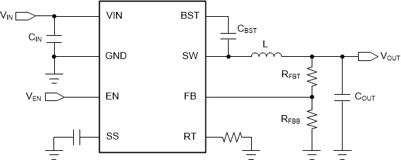
 概略回路図
概略回路図
TPS62933 の効率 (VIN = 24V、fSW = 500kHz)