SLVSBG2A September 2013 – June 2016 TPS65154
PRODUCTION DATA.
- 1 Device Overview
- 2 Revision History
- 3 Pin Configuration and Functions
- 4 Specifications
-
5 Detailed Description
- 5.1 Overview
- 5.2 Functional Block Diagram
- 5.3 Feature Description
- 5.4 Device Functional Modes
- 5.5
Programming
- 5.5.1 Configuration
- 5.5.2
Programming Examples (Excluding VCOM)
- 5.5.2.1 Writing to a Single RAM Register
- 5.5.2.2 Writing to Multiple RAM Registers
- 5.5.2.3 Saving Contents of all RAM Registers to EEPROM
- 5.5.2.4 Reading from a Single RAM Register
- 5.5.2.5 Reading from a Single EEPROM Register
- 5.5.2.6 Reading from Multiple RAM Registers
- 5.5.2.7 Reading from Multiple EEPROM Registers
- 5.5.3 Programming Examples - VCOM
- 5.6
Register Map
- 5.6.1
Configuration Registers (Excluding VCOM)
- 5.6.1.1 CONFIG (00h)
- 5.6.1.2 VCC (01h)
- 5.6.1.3 DLY1 (02h)
- 5.6.1.4 AVDD (03h)
- 5.6.1.5 FSW1 (04h)
- 5.6.1.6 SS2 (05h)
- 5.6.1.7 DLY2 (06h)
- 5.6.1.8 VGL (07h)
- 5.6.1.9 SS3 (08h)
- 5.6.1.10 DLY3 (09h)
- 5.6.1.11 VGH (0Ah)
- 5.6.1.12 SS4 (0Bh)
- 5.6.1.13 FSW3 (0Ch)
- 5.6.1.14 DLY4 (0Dh)
- 5.6.1.15 OVP (0Eh)
- 5.6.1.16 FDIM (OFh)
- 5.6.1.17 RESET (10h)
- 5.6.1.18 VDET (11h)
- 5.6.1.19 DLY6 (12h)
- 5.6.1.20 VMAX (13h)
- 5.6.1.21 VMIN (14h)
- 5.6.1.22 USER (15h)
- 5.6.1.23 CONTROL (FFh)
- 5.6.2 VCOM Registers
- 5.6.1
Configuration Registers (Excluding VCOM)
- 6 Application and Implementation
- 7 Power Supply Recommendations
- 8 Layout
- 9 Device and Documentation Support
- 10Mechanical, Packaging, and Orderable Information
パッケージ・オプション
メカニカル・データ(パッケージ|ピン)
- RSL|48
サーマルパッド・メカニカル・データ
- RSL|48
発注情報
6 Application and Implementation
NOTE
Information in the following Applications section is not part of the TI component specification, and TI does not warrant its accuracy or completeness. TI's customers are responsible for determining suitability of components for their purposes. Customers should validate and test their design implementation to confirm system functionality.
6.1 Application Information
The TPS65154 devices is intended primarily for use in notebook PC and tablet applications. It needs these two supply voltages
- A regulated 3.3-V or 5-V supply for the LCD bias functions
- A direct connection to the battery for the WLED driver functions
The device configuration parameters are set by I2C interface and stored in the on-chip nonvolatile memory.
6.2 Typical Application
Figure 6-1 shows the recommended application circuit for typical applications. The I2C interface is used to optimize the circuit's operating parameters for a specific application. If different component values are used, make sure that the values are within the recommended operating conditions (see Recommended Operating Conditions). If different component values are used, the compensation components may also need to be optimized for stability and best performance.
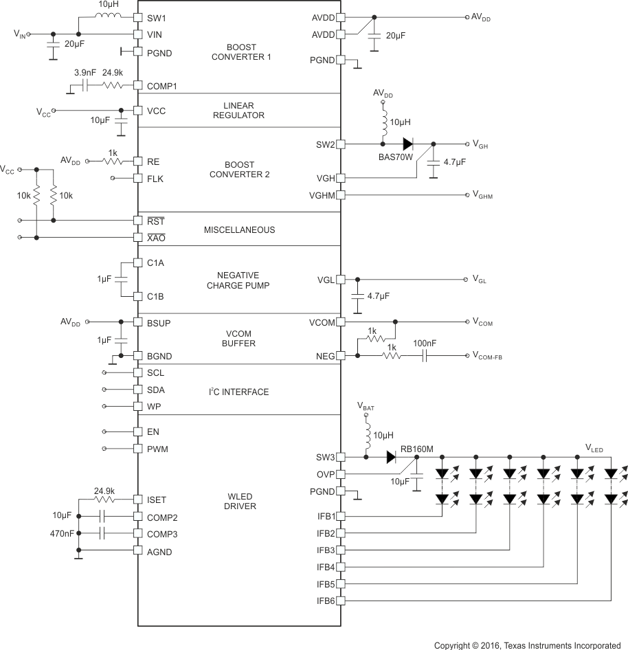 Figure 6-1 Typical Application Circuit
6.2.1 Design Requirements
This design example uses the parameters listed in Table 6-1 as the input parameters.
Table 6-1 Input Parameters
| PARAMETER | SYMBOL | VALUE |
|---|---|---|
| Input supply voltage – LCD bias functions | VIN | 3.3 V |
| Input supply voltage – WLED driver | VBAT | 9 V to 21 V |
| Boost converter 1 output voltage | AVDD | 8 V |
| Inverting charge pump output voltage | VGL | –6.8 V |
| Boost converter 2 output voltage | VGH | 20 V |
| Linear regulator output voltage | VCC | 2.5 V |
| WLED driver output current (per string) | ISET | 50 mA |
6.2.2 Detailed Design Procedure
6.2.2.1 External Component Selection
Care should be applied to the choice of external components since they greatly affect overall performance. The TPS65154 was developed with the twin goals of high performance and small/low-profile solution size. Since these two goals are often in direct opposition to one another (for example, larger inductors tend to achieve higher efficiencies), some trade-off is always necessary.
Inductors must have adequate current capability so that they do not saturate under worst-case conditions. For high efficiency, they should also have low dc resistance (DCR).
Capacitors must have adequate effective capacitance under the applicable dc bias conditions they experience in the application. MLCC capacitors typically exhibit only a fraction of their nominal capacitance under real-world conditions and this must be taken into consideration when selecting them. This problem is especially acute in low profile capacitors, in which the dielectric field strength is higher than in taller components. In general, the capacitance values shown in circuit diagrams in this data sheet refer to the effective capacitance after dc bias effects have been taken into consideration. Reputable capacitor manufacturers provide capacitance versus dc bias curves that greatly simplify component selection.
The following tables list some components suitable for use with the TPS65154. The list is not exhaustive – other components may exist that are equally suitable (or better), however, these components have been proven to work well and were used extensively during the development of the TPS65154.
Table 6-2 Linear Regulator External Component Recommendations
| REF. | DESCRIPTION | PART NUMBER | MANUFACTURER | MAX. THICKNESS |
|---|---|---|---|---|
| COUT | 10 µF, 6.3 V, ±20%, X5R, 0603 | GRM188R60J106ME84 | Murata | 0.95 mm |
Table 6-3 Boost Converter 1 External Components
| REF. | DESCRIPTION | PART NUMBER | MANUFACTURER | MAX. THICKNESS |
|---|---|---|---|---|
| L | 10 µH, 1.5 A, 0.205 Ω | NRS6012T100MMGG | Taiyo Yuden | 1.2 mm |
| COUT | 10 µF, 16 V, ±10%, X5R, 1206 | GRM319R61C106KE15D | Murata | 0.85 ±0.1 mm |
Table 6-4 Boost Converter 2 External Components
| REF. | DESCRIPTION | PART NUMBER | MANUFACTURER | MAX. THICKNESS |
|---|---|---|---|---|
| L | 10 µH, 0.6 A | NRH3010T100MN | Taiyo Yuden | 1 mm |
| COUT | 4.7 µF, 50 V, ±10%, X5R, 1206 | GRM319R61H475KA12 | Murata | 0.95 mm |
Table 6-5 Boost Converter 3 External Components
| REF. | DESCRIPTION | PART NUMBER | MANUFACTURER | MAX. THICKNESS |
|---|---|---|---|---|
| L | 10 µH, 1.5 A, 0.205 Ω | NRS6012T100MMGGJ | Taiyo Yuden | 1.2 mm |
| COUT | 4.7 µF, 50 V, ±10%, X5R, 1206 | GRM319R61H475KA12 | Murata | 0.95 mm |
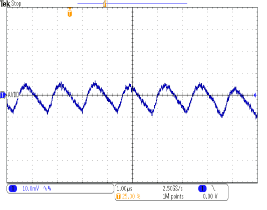
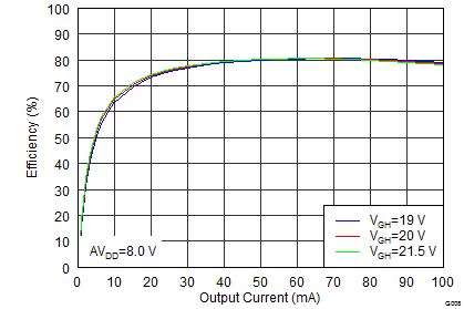
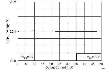
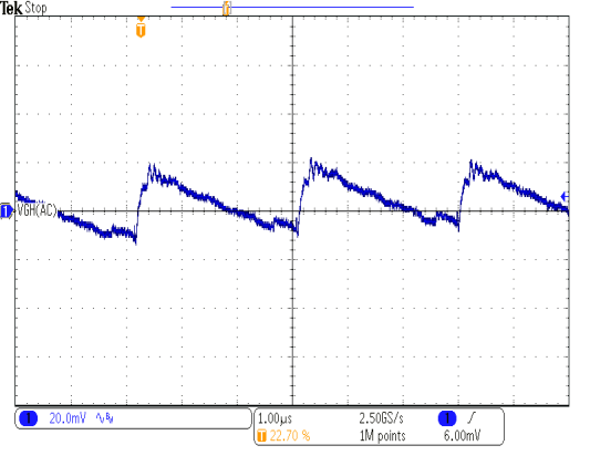
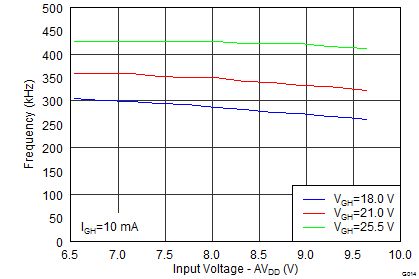
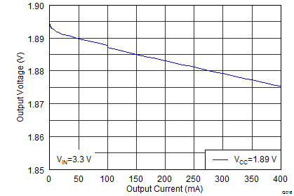
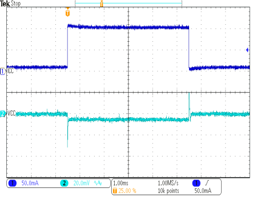
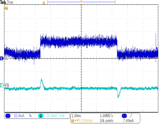
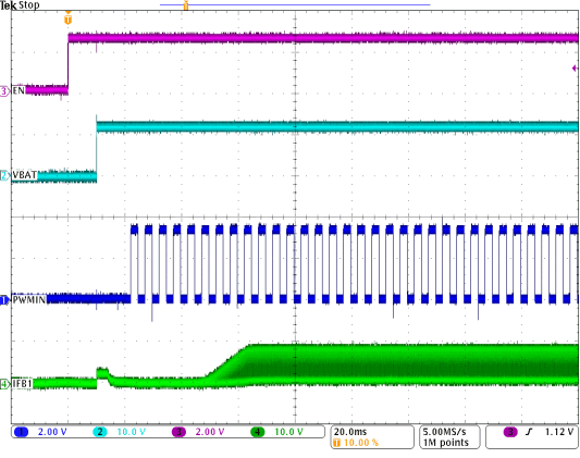
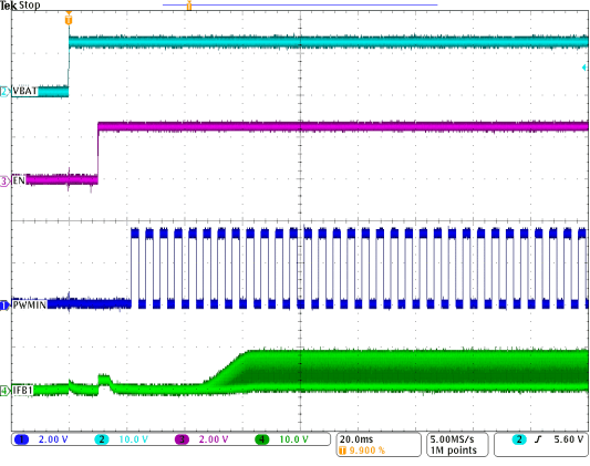
6.2.3 Application Curves
