JAJSKF7A December   2020  – April 2021 TPS7B87-Q1

PRODUCTION DATA  

  1. 特長
  2. アプリケーション
  3. 概要
  4. Revision History
  5. Pin Configuration and Functions
  6. Specifications
    1. 6.1 Absolute Maximum Ratings
    2. 6.2 ESD Ratings
    3. 6.3 Recommended Operating Conditions
    4. 6.4 Thermal Information
    5. 6.5 Electrical Characteristics
    6. 6.6 Switching Characteristics
    7. 6.7 Typical Characteristics
  7. Detailed Description
    1. 7.1 Overview
    2. 7.2 Functional Block Diagram
    3. 7.3 Feature Description
      1. 7.3.1 Power-Good (PG)
      2. 7.3.2 Adjustable Power-Good Delay Timer (DELAY)
      3. 7.3.3 Undervoltage Lockout
      4. 7.3.4 Thermal Shutdown
      5. 7.3.5 Current Limit
    4. 7.4 Device Functional Modes
      1. 7.4.1 Device Functional Mode Comparison
      2. 7.4.2 Normal Operation
      3. 7.4.3 Dropout Operation
      4. 7.4.4 Disabled
  8. Application and Implementation
    1. 8.1 Application Information
      1. 8.1.1 Input and Output Capacitor Selection
      2. 8.1.2 Dropout Voltage
      3. 8.1.3 Reverse Current
      4. 8.1.4 Power Dissipation (PD)
        1. 8.1.4.1 Thermal Performance Versus Copper Area
        2. 8.1.4.2 Power Dissipation Versus Ambient Temperature
      5. 8.1.5 Estimating Junction Temperature
      6. 8.1.6 Pulling Up the PG Pin to a Different Voltage
      7. 8.1.7 Power-Good
        1. 8.1.7.1 Setting the Adjustable Power-Good Delay
    2. 8.2 Typical Application
      1. 8.2.1 Design Requirements
      2. 8.2.2 Detailed Design Procedure
        1. 8.2.2.1 Input Capacitor
        2. 8.2.2.2 Output Capacitor
      3. 8.2.3 Application Curves
  9. Power Supply Recommendations
  10. 10Layout
    1. 10.1 Layout Guidelines
      1. 10.1.1 Package Mounting
      2. 10.1.2 Board Layout Recommendations to Improve PSRR and Noise Performance
    2. 10.2 Layout Examples
  11. 11Device and Documentation Support
    1. 11.1 Device Support
      1. 11.1.1 Device Nomenclature
      2. 11.1.2 Development Support
    2. 11.2 Documentation Support
      1. 11.2.1 Related Documentation
    3. 11.3 Receiving Notification of Documentation Updates
    4. 11.4 サポート・リソース
    5. 11.5 Trademarks
    6. 11.6 Electrostatic Discharge Caution
    7. 11.7 Glossary
  12. 12Mechanical, Packaging, and Orderable Information

パッケージ・オプション

メカニカル・データ(パッケージ|ピン)
サーマルパッド・メカニカル・データ
発注情報

概要

TPS7B87-Q1 は、車載用アプリケーションのバッテリに接続するように設計された低ドロップアウト・リニア・レギュレータです。このデバイスの入力電圧範囲は 40V まで拡張されているため、車載用システムで予測される過渡事象 (負荷ダンプなど) にも耐えられます。このデバイスは軽負荷時の静止電流がわずか 17µA であることから、スタンバイ・システムのマイクロコントローラや CAN (コントローラ・エリア・ネットワーク) トランシーバなどの常時オンのコンポーネントへの電力供給に最適なソリューションです。

このデバイスは、負荷やラインの変動 (例:コールド・クランク条件時) に出力が素早く応答できる最先端の過渡応答性能を備えています。またこのデバイスは、ドロップアウトからの回復時に出力オーバーシュートを最小限に抑える革新的なアーキテクチャを採用しています。通常動作時は、ライン、負荷、温度の全範囲にわたって誤差 ±0.85% 以下の高い DC 精度を維持します。

パワー・グッド遅延は外部コンポーネントによって調整できるため、アプリケーション固有のシステムに合わせて遅延時間を構成できます。

このデバイスは熱伝導性のパッケージで供給されるため、デバイスが回路基板に熱を効率的に伝達できます。

製品情報(1)
型番 パッケージ 本体サイズ (公称)
TPS7B87-Q1 HSOIC (8) 4.89mm×3.90mm
TO-252 (5) 6.60mm×6.10mm
利用可能なすべてのパッケージについては、このデータシートの末尾にある注文情報を参照してください。
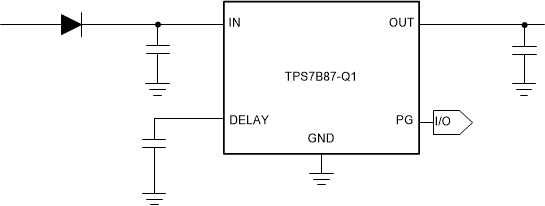
GUID-13F387E4-3586-4F4D-A419-49344E908644-low.gif基準電圧と等しい出力