-
TPS7H4010-SEP 宇宙向けに強化されたプラスチックに封止した耐放射線強化 3.5V~32V、6A 同期整流降圧コンバータ
- 1 特長
- 2 アプリケーション
- 3 概要
- 4 Revision History
- 5 Pin Configuration and Functions
- 6 Specifications
-
7 Detailed Description
- 7.1 Overview
- 7.2 Functional Block Diagram
- 7.3
Feature Description
- 7.3.1 Synchronous Step-Down Regulator
- 7.3.2 Auto Mode and FPWM Mode
- 7.3.3 Fixed-Frequency Peak Current-Mode Control
- 7.3.4 Adjustable Output Voltage
- 7.3.5 Enable and UVLO
- 7.3.6 Internal LDO, VCC_UVLO, and BIAS Input
- 7.3.7 Soft Start and Voltage Tracking
- 7.3.8 Adjustable Switching Frequency
- 7.3.9 Frequency Synchronization and Mode Setting
- 7.3.10 Internal Compensation and CFF
- 7.3.11 Bootstrap Capacitor and VBOOT-UVLO
- 7.3.12 Power-Good and Overvoltage Protection
- 7.3.13 Overcurrent and Short-Circuit Protection
- 7.3.14 Thermal Shutdown
- 7.4 Device Functional Modes
-
8 Application and Implementation
- 8.1 Application Information
- 8.2
Typical Application
- 8.2.1 Design Requirements
- 8.2.2
Detailed Design Procedure
- 8.2.2.1 Output Voltage Setpoint
- 8.2.2.2 Switching Frequency
- 8.2.2.3 Input Capacitors
- 8.2.2.4 Inductor Selection
- 8.2.2.5 Output Capacitor Selection
- 8.2.2.6 Feed-Forward Capacitor
- 8.2.2.7 Bootstrap Capacitors
- 8.2.2.8 VCC Capacitor
- 8.2.2.9 BIAS
- 8.2.2.10 Soft Start
- 8.2.2.11 Undervoltage Lockout Setpoint
- 8.2.2.12 PGOOD
- 8.2.3 Application Curves
- 9 Power Supply Recommendations
- 10Layout
- 11Device and Documentation Support
- 12Mechanical, Packaging, and Orderable Information
- 重要なお知らせ
パッケージ・オプション
デバイスごとのパッケージ図は、PDF版データシートをご参照ください。
メカニカル・データ(パッケージ|ピン)
- RNP|30
- KGD|0
サーマルパッド・メカニカル・データ
- RNP|30
発注情報
DATA SHEET
TPS7H4010-SEP 宇宙向けに強化されたプラスチックに封止した耐放射線強化 3.5V~32V、6A 同期整流降圧コンバータ
このリソースの元の言語は英語です。 翻訳は概要を便宜的に提供するもので、自動化ツール (機械翻訳) を使用していることがあり、TI では翻訳の正確性および妥当性につきましては一切保証いたしません。 実際の設計などの前には、ti.com で必ず最新の英語版をご参照くださいますようお願いいたします。
1 特長
- 放射線耐性を強化
- SEL、SE、SEGR 耐性:
LET = 43MeV-cm2/mg (最大値) - LET = 43MeV-cm2/mg まで、
SET および SEFI 特性を評価済み - すべてのウェハー・ロットについて
最大 20krad(Si) の吸収線量 (TID) を保証 - 30krad(Si) まで、吸収線量 (TID) 特性を評価済み
- SEL、SE、SEGR 耐性:
- 宇宙向けに強化されたプラスチック
- 管理されたベースライン
- Au ボンド・ワイヤと NiPdAu リード仕上げ
- モールド・コンパウンドの改良による低いガス放出
- 単一の製造、アセンブリ、テスト施設
- 長い製品ライフ・サイクル
- 長期にわたる製品変更通知
- 製品のトレーサビリティ
- 広い電圧変換範囲
- tON-MIN = 60ns (標準値)
- tOFF-MIN = 70ns (標準値)
- 低い MOSFET オン抵抗
- RDS_ON_HS = 53mΩ (標準値)
- RDS_ON_LS = 31mΩ (標準値)
- 可変周波数範囲:350kHz~2.2MHz
- 外部クロックへの同期可能
- 内部補償
- パワー・グッド・フラグ
- 高精度のイネーブルによりシステム UVLO をプログラム
- 固定または可変のソフトスタート時間
- サイクル単位の電流制限
- ヒカップ・モードによる短絡保護
- サーマル・シャットダウン保護機能
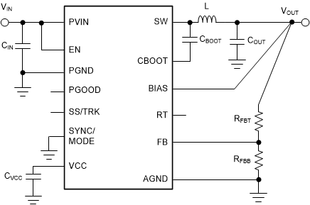
 概略回路図
概略回路図2 アプリケーション
- 人工衛星のポイント・オブ・ロード電源:FPGA、マイクロコントローラ、データ・コンバータ、ASIC 用
- 通信ペイロード
- コマンドとデータの処理
- 光学画像処理のペイロード
- レーダー画像処理ペイロード
- レーザー通信ペイロード
- ナビゲーション・ペイロード
- 科学的探査ペイロード
3 概要
TPS7H4010-SEP は、3.5V~32V の範囲の電源電圧から最大 6A の負荷電流を駆動できる、使いやすい同期整流降圧 DC/DC コンバータです。TPS7H4010-SEP はごく小さなソリューション・サイズで、非常に高い効率と出力精度を実現します。ピーク電流モード制御が採用されています。可変スイッチング周波数、外部クロックへの同期、FPWM オプション、パワー・グッド・フラグ、高精度のイネーブル、可変ソフトスタート、トラッキングなどの追加機能により、広範なアプリケーションに対して柔軟で使いやすいソリューションを実現できます。軽負荷時の自動周波数フォールドバックと、オプションの外部バイアスにより、負荷範囲の全体にわたって効率が向上します。このデバイスは、必要な外付けコンポーネントが少なく、PCB レイアウトが単純になるようピン配置が設計されており、最適な EMI と熱性能を実現しています。保護機能として、サーマル・シャットダウン、入力低電圧誤動作防止、サイクル単位の電流制限、ヒカップ短絡保護機能が搭載されています。
製品情報
| 部品番号(1) | グレード | パッケージ |
|---|---|---|
| TPS7H4010MRNPTSEP | 20krad(Si) RLAT | WQFN (30) 6.00mm × 4.00mm 質量 = 57.2mg(2) |
| TPS7H4010MRNPSEP | ||
| TPS7H4010MKGDSEP | 20krad(Si) RLAT KGD | ダイ |
(1) 利用可能なすべてのパッケージについては、このデータシートの末尾にある注文情報を参照してください。
(2) 質量の精度は ±10% です。
4 Revision History
Changes from Revision * (November 2020) to Revision A (December 2021)
- 「概要」セクションとデータシート全体のパッケージの説明を QFN から WQFN に更新Go
- 「概要」セクションの「製品情報」表に追加の注文可能デバイスを追加Go
- Added bare die information to Pin Configuration and Functions sectionGo
- Updated maximum limit for Junction temperature in Absolute Maximum Ratings tableGo
- Added specification for Junction temperature to Recommended Operating Conditions tableGo
- Updated Optimize Thermal Performance sectionGo
- Updated Related Documentation sectionGo