SLVSAD1B June 2010 – January 2016 TPS80010
PRODUCTION DATA.
- 1 Features
- 2 Applications
- 3 Description
- 4 Revision History
- 5 Pin Configuration and Functions
- 6 Specifications
- 7 Detailed Description
- 8 Application and Implementation
- 9 Power Supply Recommendations
- 10Layout
- 11Device and Documentation Support
- 12Mechanical, Packaging, and Orderable Information
パッケージ・オプション
メカニカル・データ(パッケージ|ピン)
- RSM|32
サーマルパッド・メカニカル・データ
- RSM|32
発注情報
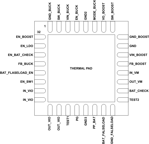
5 Pin Configuration and Functions
RSM Package
32-Pin VQFN
Bottom View

Pin Functions
| PIN | I/O | DESCRIPTION | |
|---|---|---|---|
| NAME | NO. | ||
| BAT_CHECK | 15 | O | Battery monitor switch output. Connect to ADC for battery-level check. |
| BAT_FALSELOAD | 18 | I | Battery monitor input for false-load check |
| BAT_FALSELOAD_EN | 28 | I | Battery false load switch enable |
| EN_BAT_CHECK | 30 | I | Battery-check path enable |
| EN_BOOST | 32 | I | Boost converter enable |
| EN_BUCK | 4 | I | Buck converter enable |
| EN_LDO | 31 | I | Boost post-regulation LDO enable |
| EN_SW1 | 27 | I | Buck-load switch (SW1) enable |
| FB_BOOST | 12 | I | Boost-converter feedback input |
| FB_BUCK | 29 | I | Buck converter feedback input |
| GND | 10 | – | Ground |
| GND2 | 5 | – | Device ground |
| GND3 | 20 | – | Device ground |
| GND_BOOST | 9 | – | Boost converter ground |
| GND_BUCK | 1 | – | Buck converter ground |
| GND_FALSELOAD | 17 | O | False load ground |
| IN_VIO | 25, 26 | – | Internal I/O power supply. Load switch 1 input. Connect externally to buck output |
| IN_VM | 13 | I | Boost post-regulation LDO input. Connect externally to VO_BOOST. |
| MODE_BUCK | 6 | I | Buck converter mode control. High for PWM, low for PFM. |
| OUT_VIO | 23, 24 | O | Load switch 1 output |
| OUT_VM | 14 | O | Boost post-regulation LDO output |
| PG | 21 | O | Buck Power Good indication output. High when VBUCK > 1.7 V. |
| PP_BAT | 19 | I | Battery input for level check |
| SW_BOOST | 8 | I/O | Boost converter switching node. Inductor connection. |
| SW_BUCK | 2 | O | Buck converter switching output. Inductor connection. |
| TEST1 | 22 | I/O | Test pin1 (tie to GND) |
| TEST2 | 16 | O | Test pin 2 (do not connect) |
| VIN_BOOST | 11 | – | Boost-converter power supply |
| VIN_BUCK | 3 | – | Buck converter power supply |
| VO_BOOST | 7 | O | Boost converter regulated output |