-
TS5A3160 1-Ω SPDT Analog Switch
- 1 Features
- 2 Applications
- 3 Description
- 4 Revision History
- 5 Pin Configuration and Functions
-
6 Specifications
- 6.1 Absolute Maximum Ratings
- 6.2 ESD Ratings
- 6.3 Recommended Operating Conditions
- 6.4 Thermal Information
- 6.5 Electrical Characteristics for 5-V Supply
- 6.6 Electrical Characteristics for 3.3-V Supply
- 6.7 Electrical Characteristics for 2.5-V Supply
- 6.8 Electrical Characteristics for 1.8-V Supply
- 6.9 Typical Characteristics
- 7 Parameter Measurement Information
- 8 Detailed Description
- 9 Application and Implementation
- 10Power Supply Recommendations
- 11Layout
- 12Device and Documentation Support
- 13Mechanical, Packaging, and Orderable Information
- IMPORTANT NOTICE
パッケージ・オプション
メカニカル・データ(パッケージ|ピン)
サーマルパッド・メカニカル・データ
発注情報
TS5A3160 1-Ω SPDT Analog Switch
1 Features
- Low ON-State Resistance (1 Ω)
- Isolation in the Powered-Off Mode, V+ = 0
- Specified Make-Before-Break Switching
- Control Inputs are 5-V Tolerant
- Low Charge Injection
- Excellent ON-Resistance Matching
- Low Total Harmonic Distortion
- 1.65-V to 5.5-V Single-Supply Operation
- Latch-Up Performance Exceeds 100 mA
Per JESD 78, Class II - ESD Performance Tested Per JESD 22
- 2000-V Human Body Model
(A114-B, Class II) - 1000-V Charged-Device Model (C101)
- 2000-V Human Body Model
2 Applications
- Mobile Phones
- Consumer and Computing
- Portable Instrumentation
3 Description
The TS5A3160 device is a single-pole double-throw (SPDT) analog switch that is designed to operate from 1.65 V to 5.5 V. The device offers a low ON-state resistance and an excellent channel-to-channel ON-state resistance matching. The device has excellent total harmonic distortion (THD) performance and consumes very low power. These features make this device suitable for portable audio applications.
Device Information(1)
| PART NUMBER | PACKAGE | BODY SIZE (NOM) |
|---|---|---|
| TS5A3160DBV | SOT-23 (6) | 2.90 mm × 1.60 mm |
| TS5A3160DCK | SC70 (6) | 2.00 mm × 1.25 mm |
- For all available packages, see the orderable addendum at the end of the data sheet.
Block Diagram

4 Revision History
Changes from D Revision (June 2015) to E Revision
- Changed Input leakage current UNIT value From: μA To: nA in the Electrical Characteristics for 5-V Supply tableGo
Changes from C Revision (March 2012) to D Revision
- Added Applications, Device Information table, Pin Functions table, ESD Ratings table, Thermal Information table, Typical Characteristics, Feature Description section, Device Functional Modes, Application and Implementation section, Power Supply Recommendations section, Layout section, Device and Documentation Support section, and Mechanical, Packaging, and Orderable Information section.Go
5 Pin Configuration and Functions

Pin Functions
| PIN | I/O | DESCRIPTION | |
|---|---|---|---|
| NO. | NAME | ||
| 1 | NO | I/O | Normally open switch port |
| 2 | GND | — | Ground |
| 3 | NC | I/O | Normally closed switch port |
| 4 | COM | I/O | Common switch port |
| 5 | V+ | — | Power supply |
| 6 | IN | I | Switch select. High = COM connected to NO; Low = COM connected to NC. |
6 Specifications
6.1 Absolute Maximum Ratings
over operating free-air temperature range (unless otherwise noted)(1)(2)| MIN | MAX | UNIT | |||
|---|---|---|---|---|---|
| V+ | Supply voltage(3) | –0.5 | 6.5 | V | |
| VNC
VNO VCOM |
Analog voltage(3) (4) (5) | –0.5 | V+ + 0.5 | V | |
| IK | Analog port diode current | VNC, VNO, VCOM < 0 | –50 | mA | |
| INC
INO ICOM |
On-state switch current | VNC, VNO, VCOM = 0 to V+ | –200 | 200 | mA |
| On-state peak switch current(6) | –400 | 400 | |||
| VI | Digital input voltage(3) (4) | –0.5 | 6.5 | V | |
| IIK | Digital input clamp current | VI < 0 | –50 | mA | |
| I+ | Continuous current through V+ | 100 | mA | ||
| IGND | Continuous current through GND | –100 | mA | ||
| Tstg | Storage temperature | –65 | 150 | °C | |
6.2 ESD Ratings
| VALUE | UNIT | |||
|---|---|---|---|---|
| V(ESD) | Electrostatic discharge | Human-body model (HBM), per ANSI/ESDA/JEDEC JS-001(1) | ±2000 | V |
| Charged-device model (CDM), per JEDEC specification JESD22-C101(2) | ±1000 | |||
6.3 Recommended Operating Conditions
over operating free-air temperature range (unless otherwise noted)| MIN | MAX | UNIT | ||
|---|---|---|---|---|
| VI/O | Switch input/output voltage | 0 | V+ | V |
| V+ | Supply voltage | 1.65 | 5.5 | V |
| VI | Control input voltage | 0 | 5.5 | V |
| TA | Operating temperature | –40 | 85 | °C |
6.4 Thermal Information
| THERMAL METRIC(1) | TS5A3160 | UNIT | ||
|---|---|---|---|---|
| DBV (SOT-23) | DCK (SC-70) | |||
| 6 PINS | 6 PINS | |||
| RθJA | Junction-to-ambient thermal resistance | 165 | 259 | °C/W |
6.5 Electrical Characteristics for 5-V Supply
V+ = 4.5 V to 5.5 V, TA = –40°C to 85°C (unless otherwise noted)(1)| PARAMETER | TEST CONDITIONS | TA | V+ | MIN | TYP | MAX | UNIT | ||
|---|---|---|---|---|---|---|---|---|---|
| ANALOG SWITCH | |||||||||
| VCOM, VNC, VNO | Analog signal range | 0 | V+ | V | |||||
| rpeak | Peak ON resistance |
0 ≤ (VNO or VNC) ≤ V+, ICOM = –100 mA, |
Switch ON, see Figure 13 |
25°C | 4.5 V | 0.8 | 1.1 | Ω | |
| Full | 1.5 | ||||||||
| ron | ON-state resistance | VNO or VNC = 2.5 V, ICOM = –100 mA, |
Switch ON, see Figure 13 |
25°C | 4.5 V | 0.7 | 0.9 | Ω | |
| Full | 1.1 | ||||||||
| Δron | ON-state resistance match between channels |
VNO or VNC = 2.5 V, ICOM = –100 mA, |
Switch ON, see Figure 13 |
25°C | 4.5 V | 0.05 | 0.1 | Ω | |
| Full | 0.1 | ||||||||
| ron(flat) | ON-state resistance flatness |
0 ≤ (VNO or VNC) ≤ V+, ICOM = –100 mA, |
Switch ON, see Figure 13 |
25°C | 4.5 V | 0.15 | Ω | ||
| VNO or VNC = 1 V, 1.5 V, 2.5 V, ICOM = –100 mA, |
Switch ON, see Figure 13 |
25°C | 0.1 | 0.25 | |||||
| Full | 0.25 | ||||||||
| INC(OFF), INO(OFF) |
NC, NO OFF leakage current |
VNC or VNO = 1 V, VCOM = 4.5 V, or VNO = 4.5 V, VCOM = 1 V, |
Switch OFF, see Figure 14 |
25°C | 5.5 V | –20 | 2 | 20 | nA |
| Full | –100 | 100 | |||||||
| INC(PWROFF), INO(PWROFF) |
VNC or VNO = 0 to 5.5 V, VCOM = 5.5 V to 0, |
Switch OFF, see Figure 14 |
25°C | 0 V | –1 | 0.2 | 1 | μA | |
| Full | –20 | 20 | |||||||
| INC(ON), INO(ON) |
NC, NO ON leakage current |
VNC or VNO = 0 to V+, VCOM = Open, |
Switch ON, see Figure 15 |
25°C | 5.5 V | –20 | 2 | 20 | nA |
| Full | –100 | 100 | |||||||
| ICOM(PWROFF) | COM OFF leakage current |
VCOM = 0 to 5.5 V, VNC or VNO = 5.5 V to 0, |
Switch OFF, see Figure 14 |
25°C | 0 V | –1 | 0.1 | 1 | μA |
| Full | –20 | 20 | |||||||
| ICOM(ON) | COM ON leakage current |
VCOM = 1 V, VNC or VNO = Open, or VCOM = 4.5 V, VNC or VNO = Open, |
Switch ON, see Figure 15 |
25°C | 5.5 V | –20 | 2 | 20 | nA |
| Full | –100 | 100 | |||||||
| DIGITAL CONTROL INPUT (IN)(2) | |||||||||
| VIH | Input logic high | Full | 2.4 | 5.5 | V | ||||
| VIL | Input logic low | Full | 0 | 0.8 | V | ||||
| IIH, IIL | Input leakage current | VI = 5.5 V or 0 | 25°C | 5.5 V | –2 | 0.2 | nA | ||
| Full | 100 | 100 | |||||||
| DYNAMIC | |||||||||
| tON | Turnon time | VCOM = V+, RL = 50 Ω, |
CL = 35 pF, see Figure 17 |
25°C | 5 V | 2 | 3.5 | 6 | ns |
| Full | 4.5 V to 5.5 V | 1 | 8 | ||||||
| tOFF | Turnoff time | VCOM = V+, RL = 50 Ω, |
CL = 35 pF, see Figure 17 |
25°C | 5 V | 3 | 8.5 | 13 | ns |
| Full | 4.5 V to 5.5 V | 2 | 15 | ||||||
| tMBB | Make-before-break time | VCOM = V+, RL = 50 Ω, |
CL = 35 pF, see Figure 18 |
25°C | 5 V | 2 | 7 | 12 | ns |
| Full | 5 V to 5.5 V |
2 | 15 | ||||||
| QC | Charge injection | VGEN = 0, RGEN = 0, |
CL = 1 nF, see Figure 22 |
25°C | 5 V | 36.5 | pC | ||
| CNC(OFF), CNO(OFF) |
NC, NO OFF capacitance |
VNC or VNO = V+ or GND, Switch OFF, |
See Figure 16 | 25°C | 5 V | 18 | pF | ||
| CNC(ON), CNO(ON) |
NC, NO ON capacitance |
VNC or VNO = V+ or GND, Switch ON, |
See Figure 16 | 25°C | 5 V | 55 | pF | ||
| CCOM(ON) | COM ON capacitance |
VCOM = V+ or GND, Switch ON, |
See Figure 16 | 25°C | 5 V | 55 | pF | ||
| CI | Digital input capacitance |
VI = V+ or GND, | See Figure 16 | 25°C | 5 V | 2 | pF | ||
| BW | Bandwidth | RL = 50 Ω, Switch ON, |
See Figure 19 | 25°C | 5 V | 100 | MHz | ||
| OISO | OFF isolation | RL = 50 Ω, f = 10 MHz, |
See Figure 20 | 25°C | 5 V | –64 | dB | ||
| XTALK | Crosstalk | RL = 50 Ω, f = 1 MHz, |
See Figure 20 | 25°C | 5 V | –64 | dB | ||
| THD | Total harmonic distortion | RL = 600 Ω, CL = 50 pF, |
f = 20 Hz to 20 kHz, see Figure 23 |
25°C | 5 V | 0.004% | |||
| SUPPLY | |||||||||
| I+ | Positive supply current | VI = V+ or GND | 25°C | 5.5 V | 10 | 50 | nA | ||
| Full | 500 | ||||||||
6.6 Electrical Characteristics for 3.3-V Supply
V+ = 3 V to 3.6 V, TA = –40°C to 85°C (unless otherwise noted)(1)| PARAMETER | TEST CONDITIONS | TA | V+ | MIN | TYP | MAX | UNIT | ||
|---|---|---|---|---|---|---|---|---|---|
| ANALOG SWITCH | |||||||||
| VCOM, VNC, VNO | Analog signal range | 0 | V+ | V | |||||
| rpeak | Peak ON resistance |
0 ≤ (VNO or VNC) ≤ V+, ICOM = –100 mA, |
Switch ON, see Figure 13 |
25°C | 3 V | 1.3 | 1.6 | Ω | |
| Full | 2 | ||||||||
| ron | ON-state resistance | VNO or VNC = 2 V, ICOM = –100 mA, |
Switch ON, see Figure 13 |
25°C | 3 V | 1.2 | 1.5 | Ω | |
| Full | 1.7 | ||||||||
| Δron | ON-state resistance match between channels |
VNO or VNC = 2 V, 0.8 V, ICOM = –100 mA, |
Switch ON, see Figure 13 |
25°C | 3 V | 0.1 | 0.15 | Ω | |
| Full | 0.15 | ||||||||
| ron(flat) | ON-state resistance flatness |
0 ≤ (VNO or VNC) ≤ V+, ICOM = –100 mA, |
Switch ON, see Figure 13 |
25°C | 3 V | 0.2 | Ω | ||
| VNO or VNC = 2 V, 0.8 V, ICOM = –100 mA, |
Switch ON, see Figure 13 |
25°C | 0.15 | 0.3 | |||||
| Full | 0.3 | ||||||||
| INC(OFF), INO(OFF) |
NC, NO OFF leakage current |
VNC or VNO = 1 V, VCOM = 3 V, or VNC or VNO = 3 V, VCOM = 1 V, |
Switch OFF, see Figure 14 |
25°C | 3.6 V | –20 | 2 | 20 | nA |
| Full | –50 | 50 | |||||||
| INC(PWROFF), INO(PWROFF) |
VNC or VNO = 0 to 3.6 V, VCOM = 3.6 V to 0, |
Switch OFF, see Figure 14 |
25°C | 0 V | –1 | 0.2 | 1 | μA | |
| Full | –15 | 15 | |||||||
| INC(ON), INO(ON) |
NC, NO ON leakage current |
VNC or VNO = 1 V, VCOM = Open, or VNC or VNO = 3 V, VCOM = Open, |
Switch ON, see Figure 15 |
25°C | 3.6 V | –10 | 2 | 10 | nA |
| Full | –20 | 20 | |||||||
| ICOM(PWROFF) | COM OFF leakage current |
VCOM = 0 to 3.6 V, VNC or VNO = 3.6 V to 0, |
Switch OFF, see Figure 14 |
25°C | 0 V | –1 | 0.2 | 1 | μA |
| Full | –15 | 15 | |||||||
| ICOM(ON) | COM ON leakage current |
VCOM = 1 V, VNC or VNO = Open, or VCOM = 3 V, VNC or VNO = Open, |
Switch ON, see Figure 15 |
25°C | 3.6 V | –10 | 2 | 10 | nA |
| Full | –20 | 20 | |||||||
| DIGITAL CONTROL INPUT (IN)(2) | |||||||||
| VIH | Input logic high | Full | 2 | 5.5 | V | ||||
| VIL | Input logic low | Full | 0 | 0.8 | V | ||||
| IIH, IIL | Input leakage current | VI = 5.5 V or 0 | 25°C | 3.6 V | –2 | 2 | nA | ||
| Full | –100 | 100 | |||||||
| DYNAMIC | |||||||||
| tON | Turnon time | VCOM = V+, RL = 50 Ω, |
CL = 35 pF, see Figure 17 |
25°C | 3.3 V | 2 | 4.5 | 13 | ns |
| Full | 3 V to 3.6 V |
1 | 15 | ||||||
| tOFF | Turnoff time | VCOM = V+, RL = 50 Ω, |
CL = 35 pF, see Figure 17 |
25°C | 3.3 V | 3 | 9 | 15 | ns |
| Full | 3 V to 3.6 V |
2 | 20 | ||||||
| tMBB | Make-before-break time | VCOM = V+, RL = 50 Ω, |
CL = 35 pF, see Figure 18 |
25°C | 3.3 V | 1 | 7 | 12 | ns |
| Full | 3 V to 3.6 V |
1 | 15 | ||||||
| QC | Charge injection | VGEN = 0, RGEN = 0, |
CL = 1 nF, see Figure 22 |
25°C | 3.3 V | 20 | pC | ||
| CNC(OFF), CNO(OFF) |
NC, NO OFF capacitance |
VNC or VNO = V+ or GND, Switch OFF, |
See Figure 16 | 25°C | 3.3 V | 18 | pF | ||
| CNC(ON), CNO(ON) |
NC, NO ON capacitance |
VNC or VNO = V+ or GND, Switch ON, |
See Figure 16 | 25°C | 3.3 V | 55 | pF | ||
| CCOM(ON) | COM ON capacitance |
VCOM = V+ or GND, Switch ON, |
See Figure 16 | 25°C | 3.3 V | 55 | pF | ||
| CI | Digital input capacitance |
VI = V+ or GND, | See Figure 16 | 25°C | 3.3 V | 2 | pF | ||
| BW | Bandwidth | RL = 50 Ω, Switch ON, |
See Figure 19 | 25°C | 3.3 V | 100 | MHz | ||
| OISO | OFF isolation | RL = 50 Ω, f = 10 MHz, |
See Figure 20 | 25°C | 3.3 V | –64 | dB | ||
| XTALK | Crosstalk | RL = 50 Ω, f = 1 MHz, |
See Figure 20 | 25°C | 3.3 V | –64 | dB | ||
| THD | Total harmonic distortion | RL = 600 Ω, CL = 50 pF, |
f = 20 Hz to 20 kHz, see Figure 23 |
25°C | 3.3 V | 0.01% | |||
| SUPPLY | |||||||||
| I+ | Positive supply current | VI = V+ or GND | 25°C | 3.6 V | 10 | 30 | nA | ||
| Full | 100 | ||||||||
6.7 Electrical Characteristics for 2.5-V Supply
V+ = 2.3 V to 2.7 V, TA = –40°C to 85°C (unless otherwise noted)(1)| PARAMETER | TEST CONDITIONS | TA | V+ | MIN | TYP | MAX | UNIT | ||
|---|---|---|---|---|---|---|---|---|---|
| ANALOG SWITCH | |||||||||
| VCOM, VNC, VNO | Analog signal range | 0 | V+ | V | |||||
| rpeak | Peak ON resistance |
0 ≤ (VNO or VNC) ≤ V+, ICOM = –8 mA, |
Switch ON, see Figure 13 |
25°C | 2.3 V | 1.8 | 2.5 | Ω | |
| Full | 2.7 | ||||||||
| ron | ON-state resistance | VNO or VNC = 1.8 V, ICOM = –8 mA, |
Switch ON, see Figure 13 |
25°C | 2.3 V | 1.5 | 2 | Ω | |
| Full | 2.4 | ||||||||
| Δron | ON-state resistance match between channels |
VNO or VNC = 1.8 V, ICOM = –8 mA, |
Switch ON, see Figure 13 |
25°C | 2.3 V | 0.15 | 0.2 | Ω | |
| Full | 0.2 | ||||||||
| ron(flat) | ON-state resistance flatness |
0 ≤ (VNO or VNC) ≤ V+, ICOM = –8 mA, |
Switch ON, see Figure 13 |
25°C | 2.3 V | 2.6 | Ω | ||
| VNO or VNC = 0.8 V, 1.8 V, ICOM = –8 mA, |
Switch ON, see Figure 13 |
25°C | 0.6 | 1 | |||||
| Full | 1 | ||||||||
| INC(OFF), INO(OFF) |
NC, NO OFF leakage current |
VNC or VNO = 0.5 V, VCOM = 2.2 V, or VNC or VNO = 2.2 V, VCOM = 0.5 V, |
Switch OFF, see Figure 14 |
25°C | 2.3 V | –20 | 2 | 20 | nA |
| Full | –50 | 50 | |||||||
| INC(PWROFF), INO(PWROFF) |
VNC or VNO = 0 to 2.7 V, VCOM = 2.7 V to 0, |
Switch OFF, see Figure 14 |
25°C | 0 V | –1 | 0.1 | 1 | μA | |
| Full | –10 | 10 | |||||||
| INC(ON), INO(ON) |
NC, NO ON leakage current |
VNC or VNO = 0.5 V, VCOM = Open, or VNC or VNO = 2.2 V, VCOM = Open, |
Switch ON, see Figure 15 |
25°C | 2.7 V | –10 | 2 | 10 | nA |
| Full | –20 | 20 | |||||||
| ICOM(PWROFF) | COM OFF leakage current |
VCOM = 0 to 2.7 V, VNC or VNO = 2.7 V to 0, |
Switch OFF, see Figure 14 |
25°C | 0 V | –1 | 0.1 | 1 | μA |
| Full | –10 | 10 | |||||||
| ICOM(ON) | COM ON leakage current |
VCOM = 0.5 V, VNC or VNO = Open, or VCOM = 2.2 V, VNC or VNO = Open, |
Switch ON, see Figure 15 |
25°C | 2.7 V | –10 | 2 | 10 | nA |
| Full | –20 | 20 | |||||||
| DIGITAL CONTROL INPUT (IN)(2) | |||||||||
| VIH | Input logic high | Full | 1.8 | 5.5 | V | ||||
| VIL | Input logic low | Full | 0 | 0.6 | V | ||||
| IIH, IIL | Input leakage current | VI = 5.5 V or 0 | 25°C | 2.7 V | –2 | 2 | nA | ||
| Full | –20 | 20 | |||||||
| DYNAMIC | |||||||||
| tON | Turnon time | VCOM = V+, RL = 50 Ω, |
CL = 35 pF, see Figure 17 |
25°C | 2.5 V | 2 | 6.5 | 15 | ns |
| Full | 2.3 V to 2.7 V |
1 | 17 | ||||||
| tOFF | Turnoff time | VCOM = V+, RL = 50 Ω, |
CL = 35 pF, see Figure 17 |
25°C | 2.5 V | 3 | 11 | 18 | ns |
| Full | 2.3 V to 2.7 V |
2 | 20 | ||||||
| tMBB | Make-before-break time | VCOM = V+, RL = 50 Ω, |
CL = 35 pF, see Figure 18 |
25°C | 2.5 V | 1 | 8 | 12 | ns |
| Full | 2.3 V to 2.7 V |
1 | 15 | ||||||
| QC | Charge injection | VGEN = 0, RGEN = 0, |
CL = 1 nF, see Figure 22 |
25°C | 2.5 V | 12 | pC | ||
| CNC(OFF), CNO(OFF) |
NC, NO OFF capacitance |
VNC or VNO = V+ or GND, Switch OFF, |
See Figure 16 | 25°C | 2.5 V | 18 | pF | ||
| CNC(ON), CNO(ON) |
NC, NO ON capacitance |
VNC or VNO = V+ or GND, Switch ON, |
See Figure 16 | 25°C | 2.5 V | 55 | pF | ||
| CCOM(ON) | COM ON capacitance |
VCOM = V+ or GND, Switch ON, |
See Figure 16 | 25°C | 2.5 V | 55 | pF | ||
| CI | Digital input capacitance |
VI = V+ or GND, | See Figure 16 | 25°C | 2.5 V | 2 | pF | ||
| BW | Bandwidth | RL = 50 Ω, Switch ON, |
See Figure 19 | 25°C | 2.5 V | 100 | MHz | ||
| OISO | OFF isolation | RL = 50 Ω, f = 10 MHz, |
See Figure 20 | 25°C | 2.5 V | –64 | dB | ||
| XTALK | Crosstalk | RL = 50 Ω, f = 1 MHz, |
See Figure 20 | 25°C | 2.5 V | –64 | dB | ||
| THD | Total harmonic distortion | RL = 600 Ω, CL = 50 pF, |
f = 20 Hz to 20 kHz, see Figure 23 |
25°C | 2.5 V | 0.02% | |||
| SUPPLY | |||||||||
| I+ | Positive supply current | VI = V+ or GND | 25°C | 2.7 V | 10 | 30 | nA | ||
| Full | 50 | ||||||||
6.8 Electrical Characteristics for 1.8-V Supply
V+ = 1.65 V to 1.95 V, TA = –40°C to 85°C (unless otherwise noted)(1)| PARAMETER | TEST CONDITIONS | TA | V+ | MIN | TYP | MAX | UNIT | ||
|---|---|---|---|---|---|---|---|---|---|
| ANALOG SWITCH | |||||||||
| VCOM, VNC, VNO | Analog signal range | 0 | V+ | V | |||||
| rpeak | Peak ON resistance |
0 ≤ (VNO or VNC) ≤ V+, ICOM = –2 mA, |
Switch ON, see Figure 13 |
25°C | 1.65 V | 5 | Ω | ||
| Full | 15 | ||||||||
| ron | ON-state resistance | VNO or VNC = 1.5 V, ICOM = –2 mA, |
Switch ON, see Figure 13 |
25°C | 1.65 V | 2 | 2.5 | Ω | |
| Full | 3.5 | ||||||||
| Δron | ON-state resistance match between channels |
VNO or VNC = 1.5 V, ICOM = –2 mA, |
Switch ON, see Figure 13 |
25°C | 1.65 V | 0.15 | 0.4 | Ω | |
| Full | 0.4 | ||||||||
| ron(flat) | ON-state resistance flatness |
0 ≤ (VNO or VNC) ≤ V+, ICOM = –2 mA, |
Switch ON, see Figure 13 |
25°C | 1.65 V | 5 | Ω | ||
| VNO or VNC = 0.6 V, 1.5 V, ICOM = –2 mA, |
Switch ON, see Figure 13 |
25°C | 4.5 | ||||||
| Full | |||||||||
| INC(OFF), INO(OFF) |
NC, NO OFF leakage current |
VNC or VNO = 0.3 V, VCOM = 1.65 V, or VNC or VNO = 1.65 V, VCOM = 0.3 V, |
Switch OFF, see Figure 14 |
25°C | 1.95 V | –5 | 2 | 5 | nA |
| Full | –20 | 20 | |||||||
| INC(PWROFF), INO(PWROFF) |
VNC or VNO = 0 to 1.95 V, VCOM = 1.95 V to 0, |
Switch OFF, see Figure 14 |
25°C | 0 V | –1 | 0.1 | 1 | μA | |
| Full | –5 | 5 | |||||||
| INC(ON), INO(ON) |
NC, NO ON leakage current |
VNC or VNO = 0.3 V, VCOM = Open, or VNC or VNO = 1.65 V, VCOM = Open, |
Switch ON, see Figure 15 |
25°C | 1.95 V | –5 | 2 | 5 | nA |
| Full | –20 | 20 | |||||||
| ICOM(PWROFF) | COM OFF leakage current |
VCOM = 0 to 1.95 V, VNC or VNO =1.95 V to 0, |
Switch OFF, see Figure 14 |
25°C | 0 V | –1 | 0.1 | 1 | μA |
| Full | –5 | 5 | |||||||
| ICOM(ON) | COM ON leakage current |
VCOM = 0.3 V, VNC or VNO = Open, or VCOM = 1.65 V, VNC or VNO = Open, |
Switch ON, see Figure 15 |
25°C | 1.95 V | –5 | 2 | 5 | nA |
| Full | –20 | 20 | |||||||
| DIGITAL CONTROL INPUT (IN)(2) | |||||||||
| VIH | Input logic high | Full | 1.5 | 5.5 | V | ||||
| VIL | Input logic low | Full | 0 | 0.6 | V | ||||
| IIH, IIL | Input leakage current | VI = 5.5 V or 0 | 25°C | 1.95 V | –2 | 2 | nA | ||
| Full | –20 | 20 | |||||||
| DYNAMIC | |||||||||
| tON | Turnon time | VCOM = V+, RL = 50 Ω, |
CL = 35 pF, see Figure 17 |
25°C | 1.8 V | 6 | 13 | 24 | ns |
| Full | 2.3 V to 2.7 V | 5 | 27 | ||||||
| tOFF | Turnoff time | VCOM = V+, RL = 50 Ω, |
CL = 35 pF, see Figure 17 |
25°C | 1.8 V | 6 | 15 | 27 | ns |
| Full | 2.3 V to 2.7 V | 5 | 30 | ||||||
| tMBB | Make-before-break time | VCOM = V+, RL = 50 Ω, |
CL = 35 pF, see Figure 18 |
25°C | 1.8 V | 2 | 7 | 12 | ns |
| Full | 2.3 V to 2.7 V | 2 | 15 | ||||||
| QC | Charge injection | VGEN = 0, RGEN = 0, |
CL = 1 nF, see Figure 22 |
25°C | 1.8 V | 5.5 | pC | ||
| CNC(OFF), CNO(OFF) |
NC, NO OFF capacitance |
VNC or VNO = V+ or GND, Switch OFF, |
See Figure 16 | 25°C | 1.8 V | 18 | pF | ||
| CNC(ON), CNO(ON) |
NC, NO ON capacitance |
VNC or VNO = V+ or GND, Switch ON, |
See Figure 16 | 25°C | 1.8 V | 55 | pF | ||
| CCOM(ON) | COM ON capacitance |
VCOM = V+ or GND, Switch ON, |
See Figure 16 | 25°C | 1.8 V | 55 | pF | ||
| CI | Digital input capacitance |
VI = V+ or GND, | See Figure 16 | 25°C | 1.8 V | 2 | pF | ||
| BW | Bandwidth | RL = 50 Ω, Switch ON, |
See Figure 19 | 25°C | 1.8 V | 105 | MHz | ||
| OISO | OFF isolation | RL = 50 Ω, f = 10 MHz, |
See Figure 20 | 25°C | 1.8 V | –64 | dB | ||
| XTALK | Crosstalk | RL = 50 Ω, f = 1 MHz, |
See Figure 20 | 25°C | 1.8 V | –64 | dB | ||
| THD | Total harmonic distortion | RL = 600 Ω, CL = 50 pF, |
f = 20 Hz to 20 kHz, see Figure 23 |
25°C | 1.8 V | 0.06% | |||
| SUPPLY | |||||||||
| I+ | Positive supply current | VI = V+ or GND | 25°C | 1.95 V | 5 | 15 | nA | ||
| Full | 50 | ||||||||
6.9 Typical Characteristics
 Figure 1. ron vs VCOM
 Figure 3. ron vs VCOM (V+ = 5 V)
 Figure 5. Leakage Current vs Temperature (V+ = 5 V)
 Figure 7. tON and tOFF vs Supply Voltage
 Figure 9. Bandwidth (Gain vs Frequency) (V+ = 5 V)
 Figure 11. Total Harmonic Distortion vs Frequency
 Figure 2. ron vs VCOM (V+ = 3.3 V)
 Figure 4. Leakage Current vs Temperature (V+ = 5.5 V)
 Figure 6. Charge Injection (QC) vs VCOM

 Figure 10. OFF Isolation vs Crosstalk (V+ = 5 V)

(V+ = 5 V)
7 Parameter Measurement Information
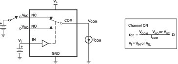 Figure 13. ON-State Resistance (ron)
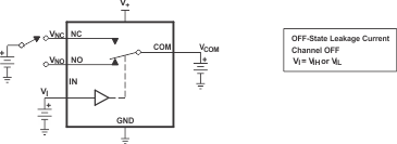 Figure 14. OFF-State Leakage Current (INC(OFF), INO(OFF), ICOM(OFF), INC(PWROFF), INO(PWROFF), ICOM(PWROFF))
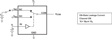 Figure 15. ON-State Leakage Current (ICOM(ON), INC(ON), INO(ON))
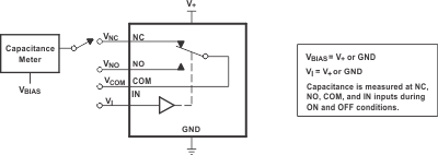 Figure 16. Capacitance (CI, CCOM(ON), CNC(OFF), CNO(OFF), CNC(ON), CNO(ON))
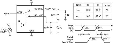

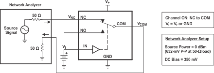 Figure 19. Bandwidth (BW)
 Figure 20. OFF Isolation (OISO)
 Figure 21. Crosstalk (XTALK)

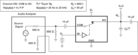 Figure 23. Total Harmonic Distortion (THD)
8 Detailed Description
8.1 Overview
The TS5A3160 is a single-pole-double-throw (SPDT) solid-state analog switch. The TS5A3160, like all analog switches, is bidirectional. When powered on, each COM pin is connected to the NC pin. For this device, NC stands for normally closed and NO stands for normally open. If IN is low, COM is connected to NC. If IN is high, COM is connected to NO.
The TS5A3160 is a make-before-break switch. This means that during switching, a connection is made before the existing connection is broken. During this brief period, the NC and NO pins are connected to each other.
8.2 Functional Block Diagram

8.3 Feature Description
The low ON-state resistance, ON-state resistance matching, and charge injection in the TS5A3160 make this switch an excellent choice for analog signals that require minimal distortion. In addition, the low THD allows audio signals to be preserved more clearly as they pass through the device.
The 1.65-V to 5.5-V operation allows compatibility with more logic levels, and the bidirectional I/Os can pass analog signals from 0 V to V+ with low distortion.
8.4 Device Functional Modes
Table 1 lists the functional modes for the TS5A3160.
Table 1. Function Table
| IN | NC TO COM, COM TO NC |
NO TO COM, COM TO NO |
|---|---|---|
| L | ON | OFF |
| H | OFF | ON |