-
TUSB213-Q1 USB 2.0高速信号コンディショナー
パッケージ・オプション
デバイスごとのパッケージ図は、PDF版データシートをご参照ください。
メカニカル・データ(パッケージ|ピン)
- RGY|14
サーマルパッド・メカニカル・データ
発注情報
DATA SHEET
TUSB213-Q1 USB 2.0高速信号コンディショナー
このリソースの元の言語は英語です。 翻訳は概要を便宜的に提供するもので、自動化ツール (機械翻訳) を使用していることがあり、TI では翻訳の正確性および妥当性につきましては一切保証いたしません。 実際の設計などの前には、ti.com で必ず最新の英語版をご参照くださいますようお願いいたします。
1 特長
- 車載アプリケーションに対応
- 下記内容でAEC-Q100認定済み
- デバイス温度グレード 2: 動作時周囲温度 -40℃~105°C
- デバイスHBM分類レベルH1C
- デバイスCDM分類レベルC3
- USB 2.0、OTG 2.0、BC 1.2と互換
- ピン・ストラップまたはI2Cで構成可能
- LS、FS、HS信号処理のサポート
- USB切断およびシャットダウン時の非常に低い消費電力
- スケーラブルなソリューション - 損失の大きいアプリケーションにはデイジーチェーン・デバイスを使用
- D1P/MおよびD2P/Mを交換可能で、ホスト/デバイスに非依存
- プリチャネルで最大5m、ポストチャネルで最大2mの長さのケーブルに対応
- 外付けのプルダウン抵抗により、4つのAC昇圧設定を選択可能
- DC昇圧とAC昇圧により最良の信号整合性を実現
2 アプリケーション
- 車載インフォテインメント
- ノートブックPC
- デスクトップPC
- ドッキング・ステーション
- タブレット
- 携帯電話
- アクティブ・ケーブル、ケーブル・エクステンダ
- バックプレーン
- TV
3 概要
TUSB213-Q1は、USBハイ・スピード(HS)信号コンディショナーで、伝送チャネルでのISI信号損失を補償するよう設計されています。 これにより、USBの電気的コンプライアンスのテストに合格するために役立ちます。
TUSB213-Q1は、特許出願中の設計により、USBロー・スピード(LS)およびフル・スピード(FS)信号でも関係なく動作します。LSおよびFS信号の特性は、TUSB213-Q1により影響を受けず、HS信号は補償されます。
信号のAC昇圧およびDC昇圧をプログラム可能なので、デバイスの性能を微調整してハイ・スピード信号をコネクタで最適化でき、多くの異なるアプリケーションで使用可能です。
さらに、TUSB213-Q1はUSB On-The-Go (OTG)やBattery Charging (BC)プロトコルとも互換性があります。
製品情報 (1)
| 型番 | パッケージ | 本体サイズ(公称) |
|---|---|---|
| TUSB213-Q1 | VQFN (14) | 3.50mm×3.50mm |
- 利用可能なすべてのパッケージについては、このデータシートの末尾にある注文情報を参照してください。
SPACER
概略回路図
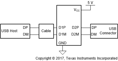
ディスプレイ

4 改訂履歴
| 日付 | 改訂内容 | 注 |
|---|---|---|
| 2017年9月 | * | 初版 |
5 Pin Configuration and Functions
RGY Package
14 Pin (VQFN)
Top View
Pin Functions
| PIN | I/O | INTERNAL PULLUP/PULLDOWN |
DESCRIPTION | |
|---|---|---|---|---|
| NAME | NO. | |||
| EQ | 1 | I | N/A | USB High Speed AC boost select via external pull down resistor. Sampled upon de-assertion of RSTN. Does not recognize real time adjustments. See application section for details. Auto selects maximum AC boost level when left floating. |
| NC | 2, 3 | N/A | N/A | Leave unconnected. |
| DC_BOOST(2)/ENA_HS | 4 | I/O | In I2C mode: Reserved for TI test purpose. In non-I2C mode: At reset: 3-level input signal DC_BOOST. USB High Speed DC signal boost selection. H (pin is pulled high) – 80 mV M (pin is left floating) – 60 mV L (pin is pulled low) – 40 mV After reset: Output signal ENA_HS. Flag indicating that channel is in High Speed mode. Asserted upon: 1. Detection of USB-IF High Speed test fixture from an unconnected state followed by transmission of USB TEST_PACKET pattern. 2. Squelch detection following USB reset with a successful HS handshake [HS handshake is declared to be successful after single chirp J chirp K pair where each chirp is within 18 μs – 128 μs]. |
|
| D2P | 5 | I/O | N/A | USB High Speed positive port. |
| D2M | 6 | I/O | N/A | USB High Speed negative port. |
| GND | 7 | PWR | N/A | Ground |
| VREG | 8 | O | N/A | 1.8-V LDO output. Only enabled when operating in High Speed mode. Requires 0.1-µF external capacitor to GND to stabilize the core. |
| D1M | 9 | I/O | N/A | USB High Speed negative port.. |
| D1P | 10 | I/O | N/A | USB High Speed positive port. |
| SDA(1) | 11 | I/O | RSTN asserted: 500 kΩ PD | I2C Mode: Bidirectional I2C data pin [I2C address = 0x2C]. In non I2C mode: Reserved for TI test purpose. |
| VCC | 12 | PWR | N/A | Supply power |
| SCL(1)/CD | 13 | I/O | RSTN asserted: 500 kΩ PD | In I2C mode: I2C clock pin [I2C address = 0x2C]. Non I2C mode: After reset: Output CD. Flag indicating that a USB device is attached (connection detected). Asserted from an unconnected state upon detection of DP or DM pull-up resistor. De-asserted upon detection of disconnect. |
| RSTN | 14 | I | 500 kΩ PU | Device disable/enable. Low – Device is at reset and in shutdown, and High – Normal operation. Recommend 0.1-µF external capacitor to GND to ensure clean power on reset if not driven. If the pin is driven, it must be held low until the supply voltage for the device reaches within specifications. |
(1) Pull-up resistors for SDA and SCL pins in I2C mode should be 4.7 kΩ (5%). If both SDA and SCL are pulled up at reset the device enters into I2C mode.
(2) Pull-down and pull-up (to 3.3 V) resistors for DC_BOOST pins must be between 22 kΩ to 47 kΩ in non I2C mode.
6 Specifications
6.1 Absolute Maximum Ratings
over operating free-air temperature and voltage range (unless otherwise noted)(1)| MIN | MAX | UNIT | ||
|---|---|---|---|---|
| Supply Voltage Range | VCC | -0.3 | 6 | V |
| Voltage Range on I/O pins | DxP, DxM, RSTN, EQ, SCL, SDA, DC_BOOST, VREG | -0.3 | 3.8 | V |
| Tstg | Storage temperature | -65 | 150 | °C |
(1) Stresses beyond those listed under Absolute Maximum Rating may cause permanent damage to the device. These are stress ratings only, which do not imply functional operation of the device at these or any other conditions beyond those indicated under Recommended Operating Condition. Exposure to absolute-maximum-rated conditions for extended periods may affect device reliability.
6.2 ESD Ratings
| VALUE | UNIT | |||
|---|---|---|---|---|
| V(ESD) | Electrostatic discharge | Human body model (HBM), per ANSI/ESDA/JEDEC JS-001, all pins(1) | ±2000 | V |
| Charged device model (CDM), per JEDEC specification JESD22-C101, all pins(2) | ±500 | |||
(1) JEDEC document JEP155 states that 500-V HBM allows safe manufacturing with a standard ESD control process.
(2) JEDEC document JEP157 states that 250-V CDM allows safe manufacturing with a standard ESD control process.
6.3 Recommended Operating Conditions
over operating free-air temperature and voltage range (unless otherwise noted)| MIN | NOM | MAX | UNIT | |||
|---|---|---|---|---|---|---|
| VCC | Supply voltage | 4.4 | 5 | 5.5 | V | |
| TA | Ambient temperature | TUSB213Q1 | -40 | 105 | °C | |
| TJ | Junction temperature | TUSB213Q1 | -40 | 125 | °C | |
6.4 Thermal Information
| THERMAL METRIC(1) | UNIT | ||
|---|---|---|---|
| RGY (VQFN) | |||
| 14 PINS | |||
| RθJA | Junction-to-ambient thermal resistance | 49.1 | °C/W |
| RθJC(top) | Junction-to-case (top) thermal resistance | 52.8 | °C/W |
| RθJB | Junction-to-board thermal resistance | 24.2 | °C/W |
| ΨJT | Junction-to-top characterization parameter | 2.2 | °C/W |
| ΨJB | Junction-to-board characterization parameter | 24.3 | °C/W |
| RθJC(bot) | Junction-to-case (bottom) thermal resistance | 7 | °C/W |
(1) For more information about traditional and new thermal metrics, see the Semiconductor and IC Package Thermal Metrics application report.
6.5 Electrical Characteristics
over operating free-air temperature and voltage range (unless otherwise noted)| PARAMETER | TEST CONDITIONS | MIN | TYP | MAX | UNIT | |
|---|---|---|---|---|---|---|
| POWER | ||||||
| IACTIVE_HS | High-speed active curent | USB channel = HS mode; 480 Mbps traffic; VCC = 5V; VCC supply stable; DC Boost = 60 mV | 18 | 30 | mA | |
| IIDLE_HS | High-speed idle current | USB channel = HS mode; no traffic; VCC = 5V; VCC supply stable; DC Boost = 60 mV | 13 | 22 | mA | |
| ISUSPEND_HS | High-speed suspend current | USB channel = HS suspend mode; VCC = 5V; VCC supply stable | 0.76 | 1.5 | mA | |
| IFS_LS | Full/Low speed current | USB channel = FS mode or LS mode; VCC = 5V | 0.77 | 1.5 | mA | |
| IDISCONNECT | Disconnect current | Host side application; No device attachment; VCC = 5V | 0.86 | 1.5 | mA | |
| IRSTN | Disable current | RSTN driven low; VCC supply stable; VCC = 5V | 22 | 80 | µA | |
| ILKG_FS | Pin fail-safe leakage current for SDA, SCL, DC_BOOST, DxP/N, RSTN | VCC = 0 V; Pin at 3.6 V | 40 | µA | ||
| RSTN | ||||||
| VIH | High-level input voltage | VCC = 4.4V | 2 | 3.6 | V | |
| VIL | Low-level input voltage | VCC = 5.5V | 0 | 0.8 | V | |
| IIH | High-level input current | VIH = 3.6 V | -4 | 4 | µA | |
| IIL | Low-level input current | VIL = 0 V | -11 | 11 | µA | |
| EQ | ||||||
| REQ | External pull-down resistor on EQ pin. | AC Boost Level 0 | 160 | Ω | ||
| AC Boost Level 1 | 1.4 | 2 | kΩ | |||
| AC Boost Level 2 | 3.7 | 3.9 | kΩ | |||
| AC Boost Level 3 | 6 | kΩ | ||||
| CD, ENA_HS | ||||||
| VOH | High-level output voltage | IO = -50µA | 2.4 | V | ||
| VOL | Low-level output voltage | IO = 50µA | 0.4 | V | ||
| SCL, SDA | ||||||
| CI2CBUS | I2C Bus capacitance | 4 | 150 | pF | ||
| VIH | SDA and SCL input high level voltage | VCC = 4.4V | 2 | 3.6 | V | |
| VIL | SDA and SCL input Low level voltage | VCC = 5.5V | 0.8 | V | ||
| VSDA_OL | SDA low-level output voltage | 4.7kΩ pullup to 3.6V; VCC = 4.4V | 0.4 | V | ||
| ISDA_OL | SDA Low level output current | VCC = 5.5V; I2C pulled up to 3.6V | 1.1 | mA | ||
| DC_BOOST | ||||||
| VIH | High-level input voltage | VCC = 5V | 2.4 | 3.6 | V | |
| VIM | Mid-level input voltage | VCC = 5V | 1.6 | V | ||
| VIL | Low-level input voltage | VCC = 5V | 0 | 0.4 | V | |
| DxP, DxM | ||||||
| CIO_DXX | Capacitance to GND | Measured with LCR meter and device powered down. 1 MHz sinusoid, 30 mVpp ripple | 2.7 | pF | ||
6.6 Switching Characteristics
over operating free-air temperature and voltage range (unless otherwise noted)| PARAMETER | TEST CONDITIONS | MIN | TYP | MAX | UNIT | |
|---|---|---|---|---|---|---|
| FBR_DXX | DxP/M Bit Rate | USB channel = HS mode; 480 Mbps traffic; VCC supply stable | 480.24 | Mbps | ||
| tRISE_DXX | DxP/M rise time | 10% - 90%; VCC = 5.5V; Max AC Gain; | 100 | ps | ||
| tFALL_DXX | DxP/M fall time | 90% - 10%; VCC = 5.5V; Max AC Gain; | 100 | ps | ||
| tRSTN_PULSE_WIDTH | Minimum width to detect a valid RSTN signal assert when the pin is actively driven | VCC = 4.4 V; Refer to Figure 1 | 20 | µs | ||
| tSTABLE | VCC stable before RSTN de-assertion | Refer to Figure 1 | 100 | µs | ||
| tVCC_RAMP | VCC ramp time | 0.2 | 100 | ms | ||
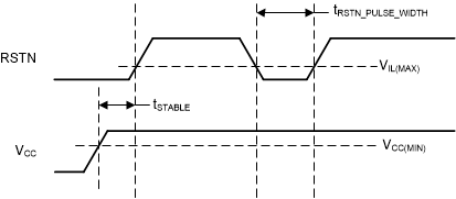 Figure 1. Power On and Reset Timing
6.7 Typical Characteristics
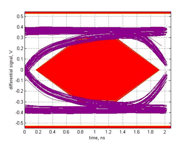 Figure 2. USB2.0 HS Eye diagram, Host far-end with 2m cable post-channel loss without TUSB213-Q1
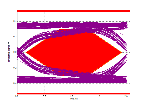 Figure 4. USB2.0 HS Eye diagram, Host far-end with 5m cable pre-channel loss without TUSB213-Q1
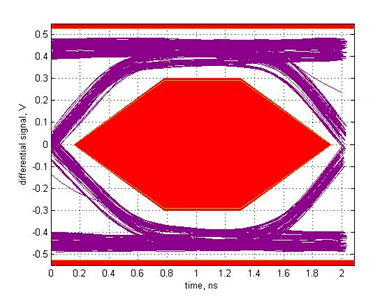 Figure 3. USB2.0 HS Eye diagram, Host far-end with 2m cable post-channel loss with TUSB213-Q1
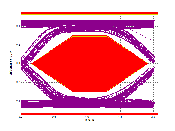 Figure 5. USB2.0 HS Eye diagram, Host far-end with 5m cable pre-channel loss with TUSB213-Q1