SLUS352C January 1997 – December 2015 UC1846 , UC2846 , UC3846 , UC3847
PRODUCTION DATA.
- 1 Features
- 2 Applications
- 3 Description
- 4 Revision History
- 5 Pin Configuration and Functions
- 6 Specifications
- 7 Detailed Description
- 8 Application and Implementation
- 9 Power Supply Recommendations
- 10Layout
- 11Device and Documentation Support
- 12Mechanical, Packaging, and Orderable Information
パッケージ・オプション
デバイスごとのパッケージ図は、PDF版データシートをご参照ください。
メカニカル・データ(パッケージ|ピン)
- DW|16
サーマルパッド・メカニカル・データ
発注情報
6 Specifications
6.1 Absolute Maximum Ratings
over operating free-air temperature range (unless otherwise noted)(1)(1) Stresses beyond those listed under Absolute Maximum Ratings may cause permanent damage to the device. These are stress ratings only, which do not imply functional operation of the device at these or any other conditions beyond those indicated under Recommended Operating Conditions. Exposure to absolute-maximum-rated conditions for extended periods may affect device reliability.
6.2 ESD Ratings
| VALUE | UNIT | |||
|---|---|---|---|---|
| V(ESD) | Electrostatic discharge | Human-body model (HBM), per ANSI/ESDA/JEDEC JS-001(1) | ±2500 | V |
| Charged-device model (CDM), per JEDEC specification JESD22-C101(2) | ±1500 | |||
(1) JEDEC document JEP155 states that 500-V HBM allows safe manufacturing with a standard ESD control process.
(2) JEDEC document JEP157 states that 250-V CDM allows safe manufacturing with a standard ESD control process.
6.3 Recommended Operating Conditions
over operating free-air temperature range (unless otherwise noted)| MIN | NOM | MAX | UNIT | ||
|---|---|---|---|---|---|
| VREF terminal external capacitance | 1 | 2.2 | µF | ||
6.4 Thermal Information
| THERMAL METRIC(1) | UCx846/7 | UNIT | ||
|---|---|---|---|---|
| N or DW (PDIP or SOIC) | J or DW (CDIP or SOIC) | |||
| 16 PINS | 16 PINS | |||
| RθJA | Junction-to-ambient thermal resistance | 41.8 | 73.1 | °C/W |
| RθJC(top) | Junction-to-case (top) thermal resistance | 28.5 | 34.2 | °C/W |
| RθJB | Junction-to-board thermal resistance | 21.8 | 38.0 | °C/W |
| ψJT | Junction-to-top characterization parameter | 13.0 | 7.7 | °C/W |
| ψJB | Junction-to-board characterization parameter | 21.7 | 37.4 | °C/W |
| RθJC(bot) | Junction-to-case (bottom) thermal resistance | N/A | N/A | °C/W |
(1) For more information about traditional and new thermal metrics, see the Semiconductor and IC Package Thermal Metrics application report, SPRA953.
6.5 Electrical Characteristics
TA=–55°C to +125°C for UC1846/7; –40°C to +85°C for the UC2846/7; and 0°C to +70°C for the UC3846/7; VIN=15 V, RT=10k, CT=4.7 nF, TA=TJ (unless otherwise noted)| PARAMETER | TEST CONDITIONS | UC1846/7 UC2846/7 |
UC3846/7 | UNIT | |||||
|---|---|---|---|---|---|---|---|---|---|
| MIN | TYP | MAX | MIN | TYP | MAX | ||||
| REFERENCE | |||||||||
| Output Voltage | TJ = 25°C, IO = 1 mA | 5.05 | 5.10 | 5.15 | 5.00 | 5.10 | 5.20 | V | |
| Line Regulation | VIN = 8 V to 40 V | 5 | 20 | 5 | 20 | mV | |||
| Load Regulation | IL = 1 mA to 10 mA | 3 | 15 | 3 | 15 | mV | |||
| Temperature Stability | Over Operating Range, (1) | 0.4 | 0.4 | mV/°C | |||||
| Total Output Variation | Line, Load, and Temperature (1) | 5.00 | 5.20 | 4.95 | 5.25 | V | |||
| Output Noise Voltage | 10 Hz ≤ f ≤10 kHz, TJ = 25°C(1) | 100 | 100 | µV | |||||
| Long Term Stability | TJ = 125°C, 1000 Hrs(1) | 5 | 5 | mV | |||||
| Short Circuit Output Current | VREF = 0 V | –10 | –45 | –10 | –45 | mA | |||
| OSCILLATOR | |||||||||
| Initial Accuracy | TJ = 25°C | 39 | 43 | 47 | 39 | 43 | 47 | kHz | |
| Voltage Stability | VIN =8 V to 40 V | –1% | 2% | –1% | 2% | ||||
| Temperature Stability | Over Operating Range (1) | –1% | –1% | ||||||
| Sync Output High Level | 3.9 | 4.35 | 3.9 | 4.35 | V | ||||
| Sync Output Low Level | 2.3 | 2.5 | 2.3 | 2.5 | V | ||||
| Sync Input High Level | Pin 8 = 0 V | 3.9 | 3.9 | V | |||||
| Sync Input Low Level | Pin 8 = 0 V | 2.5 | 2.5 | V | |||||
| Sync Input Current | Sync Voltage = 3.9 V, Pin 8 = 0 V | 1.3 | 1.5 | 1.3 | 1.5 | mA | |||
| ERROR AMPLIFIER | |||||||||
| Input Offset Voltage | 0.5 | 5 | 0.5 | 10 | mV | ||||
| Input Bias Current | –0.6 | –1 | –0.6 | –2 | µA | ||||
| Input Offset Current | 40 | 250 | 40 | 250 | nA | ||||
| Common Mode Range | VIN = 8 V to 40 V | 0 | VIN - 2 V | 0 | VIN - 2 V | V | |||
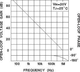
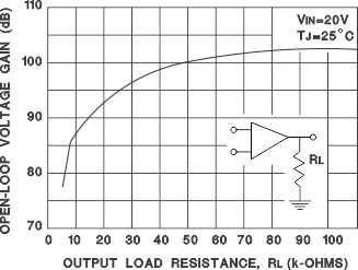
| Open Loop Voltage Gain | ΔVO = 1.2 to 3 V, VCM = 2 V | 80 | 105 | 80 | 105 | dB | |||
| Unity Gain Bandwidth | TJ = 25°C(1) | 0.7 | 1.0 | 0.7 | 1.0 | MHz | |||
| CMRR | VCM = 0 V to 38 V, VIN = 40 V | 75 | 100 | 75 | 100 | dB | |||
| PSRR | VIN = 8 V to 40 V | 80 | 105 | 80 | 105 | dB | |||
| Output Sink Current | VID = –15 mV to -5 V, VPIN7 = 1.2 V | 2 | 6 | 2 | 6 | mA | |||
| Output Source Current | VID = 15 mV to -5 V, VPIN7 = 2.5 V | –0.4 | –0.5 | –0.4 | –0.5 | mA | |||
| High Level Output Voltage | RL = (Pin 7) 15 kΩ | 4.3 | 4.6 | 4.3 | 4.6 | V | |||
| Low Level Output Voltage | RL = (Pin 7) 15 kΩ | 0.7 | 1 | 0.7 | 1 | V | |||
| CURRENT SENSE AMPLIFIER | |||||||||
| Amplifier Gain | VPIN 3 = 0 V, Pin 1 Open(2), (3) | 2.5 | 2.75 | 3.0 | 2.5 | 2.75 | 3.0 | V | |
| Maximum Differential Input Signal (VPIN 4-VPIN 3) | Pin 1 Open (2); RL (Pin 7) = 15 kW | 1.1 | 1.2 | 1.1 | 1.2 | V | |||
| Input Offset Voltage | VPIN 1 = 0.5 V, Pin 7 Open(2) | 5 | 25 | 5 | 25 | mV | |||
| CMRR | VCM = 1 V to 12 V | 60 | 83 | 60 | 83 | dB | |||
| PSRR | VIN = 8 V to 40 V | 60 | 84 | 60 | 84 | dB | |||
| Input Bias Current | VPIN 1 = 0.5 V, Pin 7 Open(2) | –2.5 | –10 | –2.5 | –10 | µA | |||
| Input Offset Current | VPIN 1 = 0.5 V, Pin 7 Open(2) | 0.08 | 1 | 0.08 | 1 | µA | |||
| Input Common Mode Range | 0 | VIN-3 | 0 | VIN-3 | V | ||||
| Delay to Outputs | TJ = 25°C (1) | 200 | 500 | 200 | 500 | ns | |||
| CURRENT LIMIT ADJUST | |||||||||
| Current Limit Offset | VPIN 3 = 0 V, VPIN 4 = 0 V, Pin 7 Open (2) | 0.45 | 0.5 | 0.55 | 0.45 | 0.5 | 0.55 | V | |
| Input Bias Current | VPIN 5 = VREF, VPIN 6 = 0 V | –10 | –30 | –10 | –30 | µA | |||
| SHUTDOWN TERMINAL | |||||||||
| Threshold Voltage | 250 | 350 | 400 | 250 | 350 | 400 | mV | ||
| Input Voltage Range | 0 | VIN | 0 | VIN | V | ||||
| Minimum Latching Current (IPIN1) | (5) | 3.0 | 1.5 | 3.0 | 1.5 | mA | |||
| Maximum Latching Current (IPIN1) | (6) | 1.5 | 0.8 | 1.5 | 0.8 | mA | |||
| Delay to Outputs | TJ = 25°C (1) | 300 | 600 | 300 | 600 | ns | |||
| OUTPUT | |||||||||
| Collector-Emitter Voltage | 40 | 40 | V | ||||||
| Collector Leakage Current | VC = 40 V (4) | 200 | 200 | µA | |||||
| Output Low Level | ISINK = 20 mA | 0.1 | 0.4 | 0.1 | 0.4 | V | |||
| ISINK = 100 mA | 0.4 | 2.1 | 0.4 | 2.1 | |||||
| Output High Level | ISOURCE = 20 mA | 13 | 13.5 | 13 | 13.5 | V | |||
| ISOURCE = 100 mA | 12 | 13.5 | 12 | 13.5 | |||||
| Rise Time | CL = 1 nF, TJ = 25°C (1) | 50 | 300 | 50 | 300 | ns | |||
| Fall Time | CL = 1 nF, TJ = 25°C (1) | 50 | 300 | 50 | 300 | ns | |||
| UNDERVOLTAGE LOCKOUT | |||||||||
| Start-Up Threshold | 7.7 | 8.0 | 7.7 | 8.0 | V | ||||
| Threshold Hysteresis | 0.75 | 0.75 | V | ||||||
| TOTAL STANDBY CURRENT | |||||||||
| Supply Current | 17 | 21 | 17 | 21 | mA | ||||
(1) These parameters, although ensured over the recommended operating conditions, are not 100% tested in production.
(2) Parameter measured at trip point of latch with VPIN 5 = VREF, VPIN 6 = 0 V.
(3) Amplifier gain defined as: G = ΔVPIN7 / ΔVPIN4; VPIN4 = 0 to 1.0 V
(4) Applies to UC1846/UC2846/UC3846 only due to polarity of outputs.
(5) Current into Pin 1 ensured to latch circuit in shutdown state.
(6) Current into Pin 1 ensured not to latch circuit in shutdown state.
6.6 Typical Characteristics

