JAJSIF6A March 2020 – August 2024 UCC21320-Q1
PRODUCTION DATA
- 1
- 1 特長
- 2 アプリケーション
- 3 概要
- 4 Pin Configuration and Functions
-
5 Specifications
- 5.1 Absolute Maximum Ratings
- 5.2 ESD Ratings (Automotive)
- 5.3 Recommended Operating Conditions
- 5.4 Thermal Information
- 5.5 Power Ratings
- 5.6 Insulation Specifications
- 5.7 Safety Limiting Values
- 5.8 Electrical Characteristics
- 5.9 Timing Requirements
- 5.10 Switching Characteristics
- 5.11 Insulation Characteristics Curves
- 5.12 Typical Characteristics
- 6 Parameter Measurement Information
- 7 Detailed Description
-
8 Application and Implementation
- 8.1 Application Information
- 8.2
Typical Application
- 8.2.1 Design Requirements
- 8.2.2
Detailed Design Procedure
- 8.2.2.1 Designing INA/INB Input Filter
- 8.2.2.2 Select External Bootstrap Diode and its Series Resistor
- 8.2.2.3 Gate Driver Output Resistor
- 8.2.2.4 Gate to Source Resistor Selection
- 8.2.2.5 Estimate Gate Driver Power Loss
- 8.2.2.6 Estimating Junction Temperature
- 8.2.2.7 Selecting VCCI, VDDA/B Capacitor
- 8.2.2.8 Dead Time Setting Guidelines
- 8.2.2.9 Application Circuits with Output Stage Negative Bias
- 8.2.3 Application Curves
- 9 Power Supply Recommendations
- 10Layout
- 11Device and Documentation Support
- 12Revision History
- 13Mechanical, Packaging, and Orderable Information
3 概要
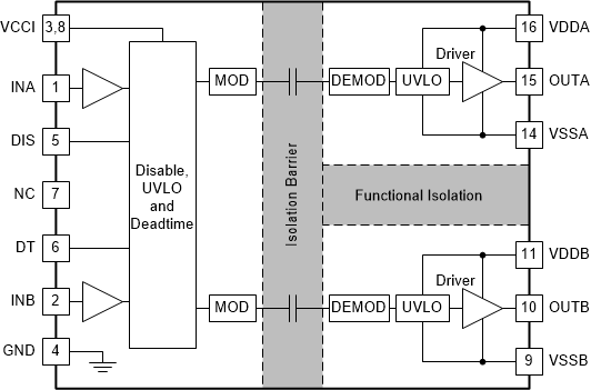
UCC21320-Q1 は、絶縁されたデュアル チャネルのゲート ドライバで、ピーク電流はソース 4A、シンク 6A です。パワー MOSFET、IGBT、SiC MOSFET (最大 5MHz) を駆動するように設計されています。
入力側は、3.75kVRMS の基本絶縁バリアによって 2 つの出力ドライバと分離されており、同相過渡耐性 (CMTI) は 125V/ns 以上です。2 つの 2 次側ドライバ間は、内部的に機能絶縁されているため、1500VDC までの電圧で動作します。
すべてのドライバは、2 つのローサイド ドライバ、2 つのハイサイド ドライバ、またはデッドタイム (DT) をプログラム可能な 1 つのハーフ ブリッジ ドライバとして構成可能です。ディセーブル ピンによって、両方の出力が同時にシャットダウンし、オープンまたは接地したときには通常動作します。フェイルセーフ手法として、1 次側のロジック障害が発生すると、両方の出力が強制的に Low になります。
各デバイスは、最大 25V の VDD 電源電圧に対応できます。VCCI 入力範囲が 3V~18V と広いため、このドライバはアナログとデジタル両方のコントローラとの接続に適しています。すべての電源電圧ピンには、低電圧誤動作防止 (UVLO) 保護機能が搭載されています。
これらの高度な機能により、UCC21320-Q1 は、高効率、高電力密度、優れた堅牢性を実現します。
製品情報(1)
| 部品番号 | パッケージ | 本体サイズ (公称) |
|---|---|---|
| UCC21320DWK-Q1 | DWK (SOIC 14) | 10.30mm × 7.50 mm |
(1) 利用可能なすべてのパッケージについては、データシートの末尾にある注文情報を参照してください。
 機能ブロック図