JAJSKQ8B October 2019 – March 2021 UCC23313-Q1
PRODUCTION DATA
- 1 特長
- 2 アプリケーション
- 3 概要
- 4 Revision History
- 5 Pin Configuration and Function
-
6 Specifications
- 6.1 Absolute Maximum Ratings
- 6.2 ESD Ratings
- 6.3 Recommended Operating Conditions
- 6.4 Thermal Information
- 6.5 Power Ratings
- 6.6 Insulation Specifications
- 6.7 Safety-Related Certifications
- 6.8 Safety Limiting Values
- 6.9 Electrical Characteristics
- 6.10 Switching Characteristics
- 6.11 Insulation Characteristics Curves
- 6.12 Typical Characteristics
- 7 Parameter Measurement Information
- 8 Detailed Description
- 9 Application and Implementation
- 10Power Supply Recommendations
- 11Layout
- 12Mechanical, Packaging, and Orderable Information
パッケージ・オプション
デバイスごとのパッケージ図は、PDF版データシートをご参照ください。
メカニカル・データ(パッケージ|ピン)
- DWY|6
サーマルパッド・メカニカル・データ
発注情報
3 概要
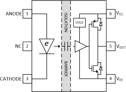
UCC23313-Q1 は、IGBT、MOSFET、SiC MOSFET 用の、フォトカプラ互換、シングル・チャネル絶縁型ゲート・ドライバです。ソース 4.5A、シンク 5.3A のピーク電流を出力でき、3.75kVRMS の基本絶縁定格を持っています。電源電圧範囲が 33V と高いため、バイポーラ電源を使用して IGBT および SiC パワー FET を効果的に駆動できます。UCC23313-Q1 は、ローサイドとハイサイドの両方のパワー FET を駆動できます。主な機能と特性は、標準的なフォトカプラ・ベースのゲート・ドライバに比べて性能と信頼性を大幅に向上させると同時に、回路設計とレイアウト設計の両方でピン互換性を維持しています。同相過渡耐性 (CMTI) が高く、伝搬遅延時間が短く、パルス幅歪みが小さいという特長があります。厳密なプロセス制御により、部品間スキューも小さくなっています。入力段はダイオード・エミュレーション (e-diode) であり、フォトカプラ・ゲート・ドライバで使われている従来型 LED に比べて、長期的な信頼性と優れた経時特性を実現します。本デバイスは、材料グループ I (比較トラッキング指数 (CTI) > 600V) のモールド・コンパウンドを採用した、沿面距離と空間距離がどちらも 8.5mm を超えるストレッチ SO6 パッケージで供給されます。UCC23313-Q1 は高性能でありかつ信頼性が高いため、トラクション・インバータ、オンボード・チャージャ、DC 充電ステーション、車載 HVAC、暖房システムなど、車載用モータ駆動に理想的です。高い温度で動作するため、従来のフォトカプラでは対応できなかったアプリケーションで活用する機会が広がります。
| 部品番号 | パッケージ | 本体サイズ (公称) |
|---|---|---|
| UCC23313-Q1 | ストレッチ SO-6 | 7.5mm × 4.68mm |
 機能ブロック図