JAJSBW9A February 2013 – September 2024 UCC27532
PRODUCTION DATA
- 1
- 1 特長
- 2 アプリケーション
- 3 概要
- 4 Pin Configuration and Functions
- 5 Specifications
- 6 Detailed Description
- 7 Application and Implementation
- 8 Layout
- 9 Device and Documentation Support
- 10Revision History
- 11Mechanical, Packaging, and Orderable Information
パッケージ・オプション
デバイスごとのパッケージ図は、PDF版データシートをご参照ください。
メカニカル・データ(パッケージ|ピン)
- DBV|6
サーマルパッド・メカニカル・データ
発注情報
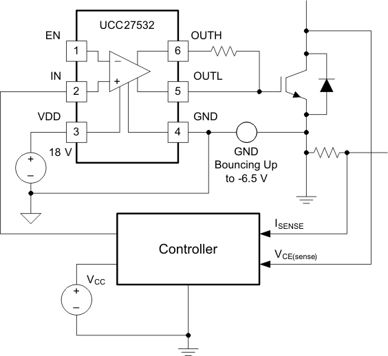
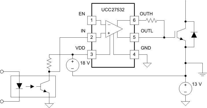
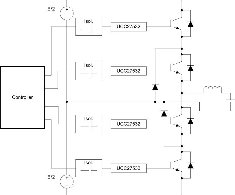
7.2 Typical Applications
 Figure 7-1 Driving IGBT Without Negative Bias
 Figure 7-2 Driving IGBT With 13-V Negative Turn-Off Bias
 Figure 7-3 Using UCC27532 Drivers in an Inverter