JAJSTL8C February   1997  – October 2024 XTR105

PRODUCTION DATA  

  1.   1
  2. 特長
  3. アプリケーション
  4. 概要
  5. Pin Configuration and Functions
  6. Specifications
    1. 5.1 Absolute Maximum Ratings #GUID-80F0CD5F-C345-42B2-B6A9-580512790460/R_DESCRIPTION_LI1
    2. 5.2 Recommended Operating Conditions
    3. 5.3 Thermal Information
    4. 5.4 Electrical Characteristics
    5. 5.5 Typical Characteristics
  7. Detailed Description
    1. 6.1 Overview
    2. 6.2 Functional Block Diagram
    3. 6.3 Feature Description
      1. 6.3.1 Linearization
        1. 6.3.1.1 High-Resistance RTDs
      2. 6.3.2 Voltage Regulator
      3. 6.3.3 Open-Circuit Protection
      4. 6.3.4 Reverse-Voltage Protection
      5. 6.3.5 Surge Protection
    4. 6.4 Device Functional Modes
  8. Application and Implementation
    1. 7.1 Application Information
      1. 7.1.1 External Transistor
      2. 7.1.2 Loop Power Supply
      3. 7.1.3 2-Wire and 3-Wire RTD Connections
      4. 7.1.4 Radio Frequency Interference
      5. 7.1.5 Error Analysis
    2. 7.2 Typical Applications
    3. 7.3 Layout
      1. 7.3.1 Layout Guidelines
  9. Device and Documentation Support
    1. 8.1 Documentation Support
      1. 8.1.1 Related Documentation
    2. 8.2 ドキュメントの更新通知を受け取る方法
    3. 8.3 サポート・リソース
    4. 8.4 Trademarks
    5. 8.5 静電気放電に関する注意事項
    6. 8.6 用語集
  10. Revision History
  11. 10Mechanical, Packaging, and Orderable Information

パッケージ・オプション

メカニカル・データ(パッケージ|ピン)
サーマルパッド・メカニカル・データ
発注情報

Surge Protection

Remote connections to current transmitters are sometimes subjected to voltage surges. Limit the maximum surge voltage applied to the XTR105 to the lowest practical value. Various zener diodes and surge clamping diodes are specially designed for this purpose. Select a clamp diode with as low a voltage rating as possible for best protection. For example, a 36V protection diode allows proper transmitter operation at normal loop voltages, yet provides an appropriate level of protection against voltage surges. The XTR105 is specified to an absolute maximum loop voltage of 40V.

Most surge protection zener diodes have a diode characteristic in the forward direction that conducts excessive current, possibly damaging receiving-side circuitry, if the loop connections are reversed. If a surge protection diode is used, use a series diode or diode bridge for protection against reversed connections.
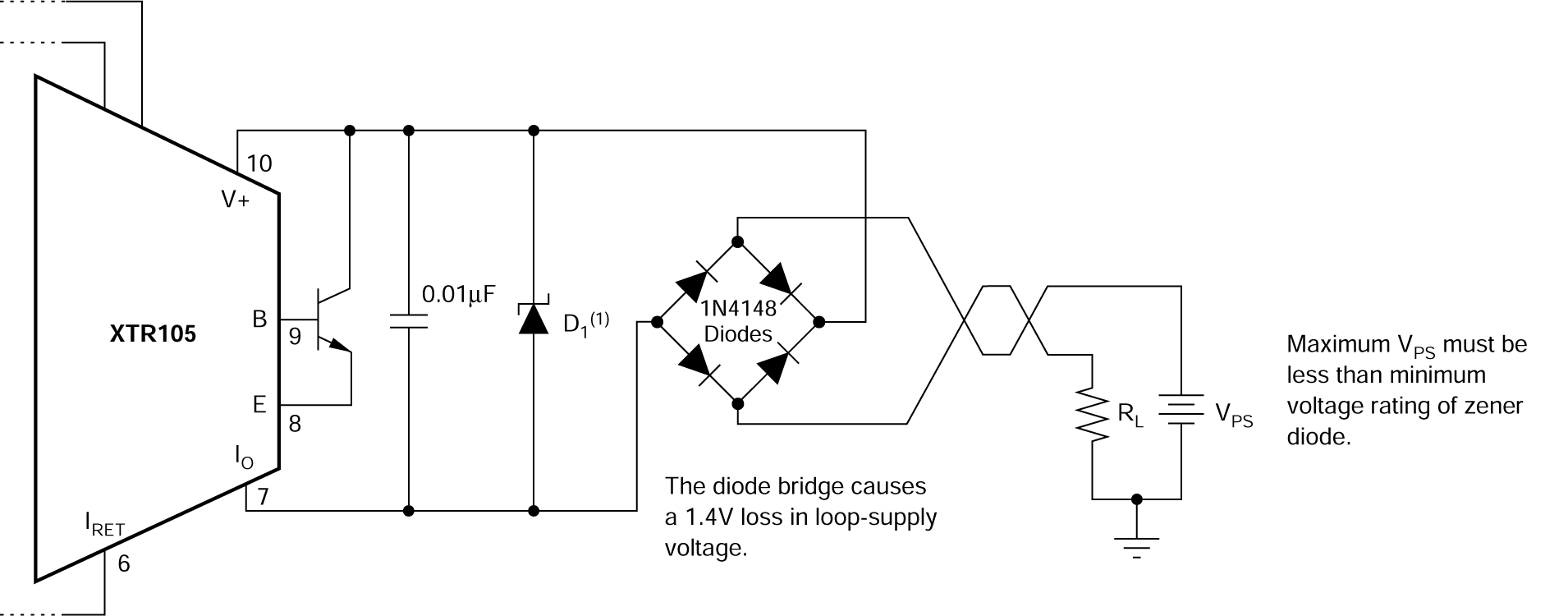
XTR105 Reverse Voltage Operation and
          Overvoltage Surge Protection
(1) 36V Zener diode, such as 1N4753A or P6KE39A. Use lower-voltage Zener diodes with loop power-supply voltages < 30V for increased protection.
Figure 6-4 Reverse Voltage Operation and Overvoltage Surge Protection