-
INA220-Q1 車載用グレード、26V、双方向、ゼロドリフト、ローサイドまたはハイサイド、I2C互換電流/電力モニタ
- 1 特長
- 2 アプリケーション
- 3 概要
- 4 改訂履歴
- 5 Related Products
- 6 Pin Configuration and Functions
- 7 Specifications
-
8 Detailed Description
- 8.1 Overview
- 8.2 Functional Block Diagram
- 8.3 Feature Description
- 8.4 Device Functional Modes
- 8.5 Programming
- 8.6 Register Maps
- 9 Application and Implementation
- 10Power Supply Recommendations
- 11Layout
- 12デバイスおよびドキュメントのサポート
- 13メカニカル、パッケージ、および注文情報
- 重要なお知らせ
DATA SHEET
INA220-Q1 車載用グレード、26V、双方向、ゼロドリフト、ローサイドまたはハイサイド、I2C互換電流/電力モニタ
このリソースの元の言語は英語です。 翻訳は概要を便宜的に提供するもので、自動化ツール (機械翻訳) を使用していることがあり、TI では翻訳の正確性および妥当性につきましては一切保証いたしません。 実際の設計などの前には、ti.com で必ず最新の英語版をご参照くださいますようお願いいたします。
1 特長
2 アプリケーション
- 電動パワー・ステアリング(EPS)システム
- 車体制御モジュール
- ブレーキ・システム
- 横滑り防止装置(ESC)システム
3 概要
INA220-Q1デバイスは、I2CまたはSMBUS互換のインターフェイスを搭載した、電流シャントおよび電力モニタです。INA220-Q1デバイスは、シャントの電圧降下と電源電圧の両方を監視します。プログラム可能な較正値と、内部的なマルチプライヤとの組み合わせにより、値をアンペア単位で直接読み出すことが可能です。追加の乗算レジスタにより、電力がワット単位で計算されます。I2CまたはSMBUS互換のインターフェイスは、16のアドレスをプログラム可能です。INA220-Q1デバイスには独立のシャント入力があり、ローサイド・センシングのシステムで使用可能です。
INA220-Q1デバイスは0~26Vの範囲で変動するバス上でシャントの両端の電圧を検出できるため、ローサイド・センシングやCPU電源に便利です。このデバイスは3~5.5Vの単一電源で動作し、消費電流は最大1mAです。INA220-Q1は-40℃~+125℃で動作します。
製品情報(1)
| 型番 | パッケージ | 本体サイズ(公称) |
|---|---|---|
| INA220-Q1 | VSSOP (10) | 3.00mm×3.00mm |
- 提供されているすべてのパッケージについては、データシートの末尾にある注文情報を参照してください。
4 改訂履歴
Changes from A Revision (June 2012) to B Revision
- Changed 部品番号をINA220-Q1にGo
- 「ESD定格」表、「機能説明」セクション、「デバイスの機能モード」セクション、「アプリケーションと実装」セクション、「電源に関する推奨事項」セクション、「レイアウト」セクション、「デバイスおよびドキュメントのサポート」セクション、「メカニカル、パッケージ、および注文情報」セクションを追加Go
- Changed ドキュメント全体で「2線式」を「I2CまたはSMBUS互換」にGo
- Deleted 「注文情報」表をGo
- 図の誤りを訂正Go
- Added automotive part numbers to Related ProductsGo
- Changed pin names in Pin Configuration and Functions Go
- Added common-mode definition to Absolute Maximum Ratings Go
- Changed IN+ and IN– pin input impedance to input bias current Go
- Changed Power register to Bus Voltage register Go
- Replaced Programming the INA220B-Q1 with Programming the INA220-Q1 Calibration RegisterGo
- Replaced PROGRAMMING THE INA220 POWER MEASUREMENT ENGINE with Calibration Register and ScalingGo
- Updated Table 2 based on one-time sample of devicesGo
- Changed Power register to Bus Voltage register Go
- Corrected register values in Detailed Design Procedure and Table 8Go
- Changed Configure, Measure, and Calculate Example table to Table 8 and removed first columnGo
Changes from * Revision (June 2012) to A Revision
- デバイスがプレビューから量産に変更Go
5 Related Products
| PART NUMBER | DESCRIPTION |
|---|---|
| INA212-Q1 | Automotive, 26-V, Bi-Directional, Zero-Drift, Precision, Low-/High-Side, Volt. Out Current Sense Amp |
| INA225-Q1 | Automotive, 36-V Prog. Gain, Bi-Directional, Zero-Drift, High-Speed Voltage Out Current Sense Amp |
| INA226-Q1 | Automotive, 36-V, Ultra-High Accuracy, Low-/High-Side, I2C Out Current/Power Monitor w/ Alert |
| INA282-Q1 | Automotive, 80-V, Bi-Directional, High Accuracy, Low-/High-Side, Voltage Out Current Shunt Monitor |
| INA300-Q1 | Automotive, 36-V Low-/High-Side, Overcurrent Protection Comparator |
| INA3221-Q1 | Automotive 26-V, Triple, Bi-Directional, Zero-Drift, I2C Out Current/Voltage Monitor w/ Alerts |
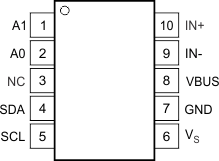
6 Pin Configuration and Functions
DGS Package
10-Pin VSSOP
Top View

Pin Functions
| PIN | I/O | DESCRIPTION | |
|---|---|---|---|
| NO. | NAME | ||
| 1 | A1 | Digital Input | Address pin. Connect to GND, SCL, SDA, or VS. Table 1 shows pin settings and corresponding addresses. |
| 2 | A0 | Digital Input | Address pin. Connect to GND, SCL, SDA, or VS. Table 1 shows pin settings and corresponding addresses. |
| 3 | NC | — | No internal connection |
| 4 | SDA | Digital I/O | Serial bus data line |
| 5 | SCL | Digital Input | Serial bus clock line |
| 6 | VS | Analog | Power supply, 3 V to 5.5 V |
| 7 | GND | Analog | Ground |
| 8 | VBUS | Analog Input | Bus voltage input |
| 9 | IN– | Analog Input | Negative differential shunt voltage. Connect to negative side of shunt resistor. Bus voltage is measured from this pin to ground. |
| 10 | IN+ | Analog Input | Positive differential shunt voltage. Connect to positive side of shunt resistor. |
