DLPA060B July 2015 – November 2024 DLP7000UV , DLP9000XUV , DLP9500UV
5 High Demagnification Systems
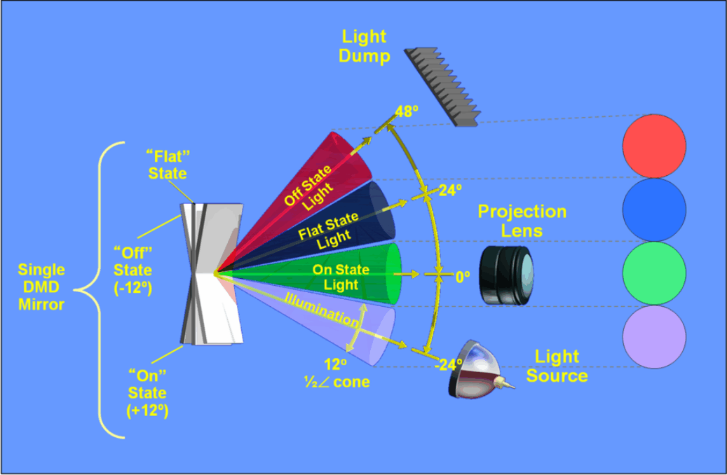
Projection systems using DLP technology typically use an illumination design as shown in Figure 5-1. Note that the flat state is not an operational DMD micromirror state, but must be accounted for when designing an optical system.
 Figure 5-1 Typical Projection System Optics
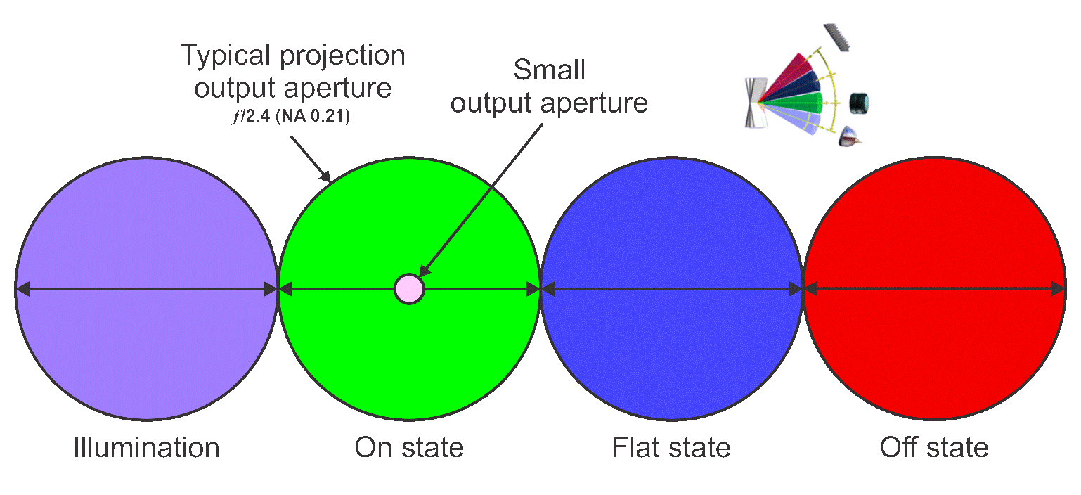
However, some lithography and 3D print systems use demagnification of the DMD array image to address very small features down to 1µm or smaller. Figure 5-2 demonstrates the small size for the output aperture of a high demagnification system versus the size of a typical projection optical system.
 Figure 5-2 Light Distribution at Projection Lens Entrance Pupil (Typical Projection System vs High Demagnification)
Considerations for these relatively small apertures typical of high demagnification are divided into two areas: incoherent sources and coherent sources.