DLPA060B July 2015 – November 2024 DLP7000UV , DLP9000XUV , DLP9500UV
5.2 Coherent Sources (Lasers)
When a DMD is illuminated with coherent, collimated, narrow-band light, the reflected result is a two-dimensional pattern of spots called diffraction orders. A continuum of conditions from a full blaze to a complete anti-blaze condition can exist depending on the pixel pitch, DMD micromirror tilt angle, illumination wavelength, and the incident angle of the illumination light.
A blaze condition exists when one diffraction order contains the majority of the energy in the overall diffraction pattern. Modeling indicates that this single order can contain nearly three-quarters of the output energy, with the remaining quarter being distributed into all of the other orders. This is the best possible case. Optical systems designed to operate at a blaze condition can use much smaller angular apertures, but likely requires DMD alignment capabilities with both illumination and projection optical path angle adjustments to correct for differences in nominal tilt angle variations from one DMD to another.
An anti-blaze condition exists when the four brightest orders contain equal amount of energy in the diffraction pattern. Modeling indicates that these four adjacent orders can each contain roughly one sixth of the total output energy (approximately two-thirds in total), with the remaining third being distributed in each of the remaining orders.
Basic DMD diffraction is discussed in more detail in Using Lasers with DLP DMD Technology (DLPA037).
For the UVA capable DMDs, the maximum specified tilt variation between individual micromirrors is ±1°. In the UVA region, this tilt angle difference is such that customers can receive a DMD that results in a condition that ranges from anti-blaze condition to blaze condition. Therefore, the system output optics must have sufficient aperture to collect, at the very least, the four brightest orders in an anti-blaze condition. For example, at 363 nm, a 10.8µm pitch device requires an angular aperture at least 2.7° in diameter. By increasing the diameter to 3.9°, four to five orders are captured, which is recommended. This recommended diameter is calculated by sin-1(2λ/d), where λ is the wavelength and d is the pixel pitch.
Coherent light sources require additional design considerations. The reflected output results in a set of diffraction orders rather than a single reflected bundle of light. These orders each have the same angular extent as the input bundle. Consequently, a collimated beam, which has virtually no angular extent, results in collimated diffraction orders.
The output aperture sees some number of these diffraction orders. If the angular diameter is smaller than sin-1(λ/d) (where d is the pixel pitch of the DMD), then this is only possible to capture one order in the output aperture, as illustrated in the panels of Figure 5-6.
If the incident illumination angle is fixed, then variations in tilt angle do not cause the diffraction orders to move, but do cause the energy distribution to shift between the orders. Consequently, if the order captured is near a blaze condition, then most of the energy available is captured in this one order (panel (a) in Figure 5-6). If the condition is near an anti-blaze point, then this small aperture only captures a fraction of the output (panel (b) in Figure 5-6).
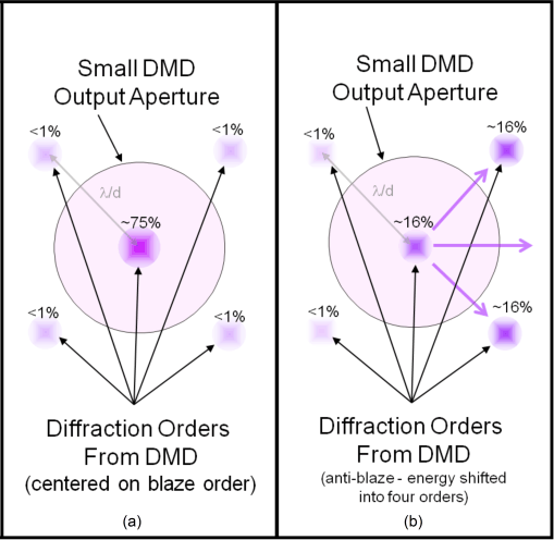 Figure 5-6 Diffraction Orders with Coherent Illumination
To provide tolerance in the system design, TI recommends that the output aperture be expanded to capture four to five orders as shown in Figure 5-7. As shown in the previous example, a 10.8µm pixel pitch DMD with collimated light at 363 nm, the minimum angular diameter of about 2.7° captures one or four orders, and 3.9° captures four or five orders. Equation 3 gives the recommended minimum angular diameter:
where:
- θinput is the angular extent of the input illumination bundle.
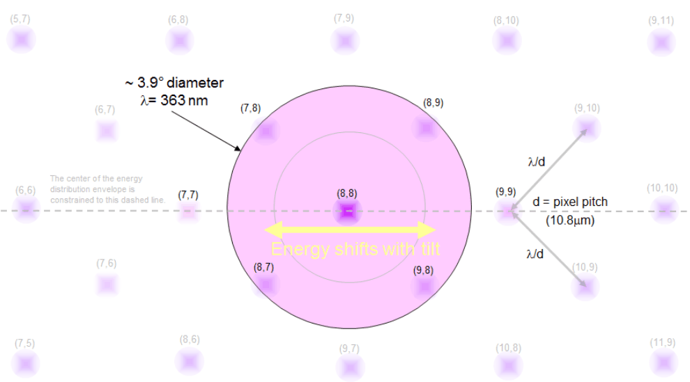 Figure 5-7 Expanded Output Aperture Capturing Five Orders
Although the orders do not move with variations in tilt angle, the orders do move with changes in the illumination angle. If the illumination is moved by an angle of θ, then the orders at the output move by approximately –θ. Therefore, TI recommends to include a mechanism to adjust the input illumination angle by ±2°, which allows the four to five orders with the highest intensity to be captured in the output aperture.
Once the illumination angle and the projection angles are established, the projected DMD orders must not move due to differences in DMD tilt angle. However, the power in each order can vary due to DMD tilt angle. Figure 5-8, Figure 5-9, and Figure 5-10 show the power and the positions of the major orders as affected by tilt angles of 11, 12, and 13 degrees of a 7.56µm pitch DMD for the specific wavelength of 365 nm. The center of the projection aperture is shown as a + symbol and the center of the projection is defined by the purple diamond shape. The orders are purple circles where the area of each circle symbolizes the relative amount of power in that specific order. Once the illumination and projection angles are established and fixed in place, notice with tilt angle change (11-12-13°) how the orders do not shift within the projection aperture but how the power moves from certain orders to other orders. This indicates the importance of having the appropriate projection aperture size that allows maximization of output power collection while taking into account DMD tilt angle as well as illumination and projection alignments.
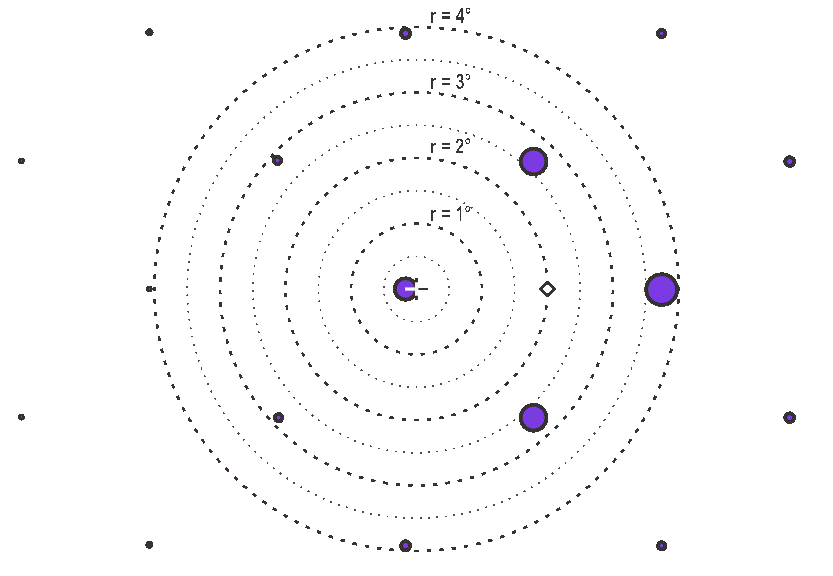 Figure 5-8 Order power diagram, 11° tilt angle, λ =
365nm, 7.56µm pixel pitch
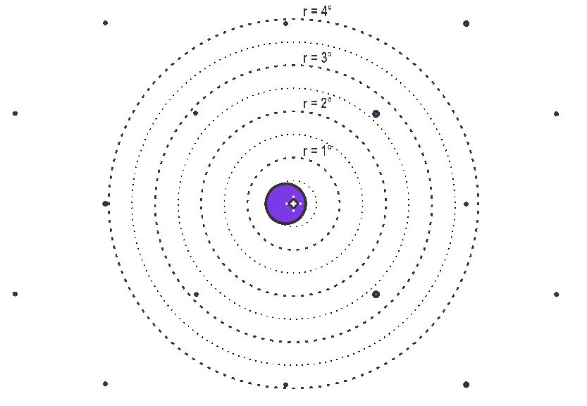 Figure 5-9 Order power diagram, 12° tilt angle, λ =
365nm, 7.56µm pixel pitch
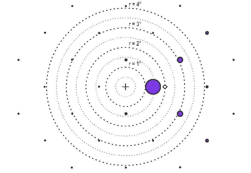 Figure 5-10 Order power diagram, 13° tilt angle, λ =
365nm, 7.56µm pixel pitch
Figure 5-10 Order power diagram, 13° tilt angle, λ =
365nm, 7.56µm pixel pitchFigure 5-11, Figure 5-12, and Figure 5-13 show the power and the positions of the major orders as affected by tilt angles of 11, 12, and 13 degrees for 10.8um pixel DMDs.
 Figure 5-11 Order power diagram, 11° tilt angle, λ =
365nm, 10.8µm pixel pitch
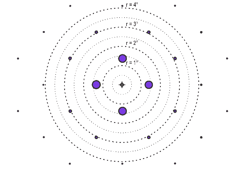 Figure 5-12 Order power diagram, 12° tilt angle, λ =
365nm, 10.8µm pixel pitch
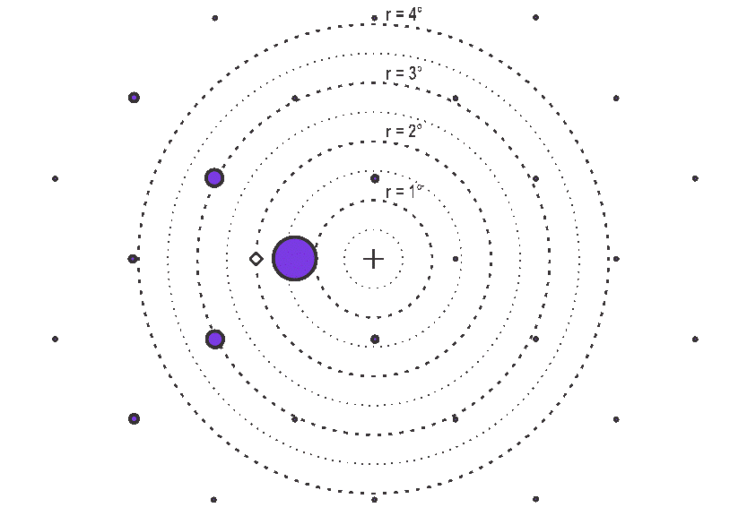 Figure 5-13 Order power diagram, 13° tilt angle, λ =
365nm, 10.8µm pixel pitch
Figure 5-13 Order power diagram, 13° tilt angle, λ =
365nm, 10.8µm pixel pitchAs with the incoherent case, the angular diameter of the output aperture sets a practical limit on the demagnification level that can be achieved. For example, at 363 nm the maximum demagnification for a 10.8µm pixel pitch DMD using collimated light is a factor of approximately 13.9x. If the incident beam has angular extent, then the diameter must be added to the output aperture before determining the de-magnification achievable.
In general, the maximum demagnification achievable can be determined by the ƒ-number of the focusing optics relative to the fabrication surface, and then setting the distance to the DMD so that the aperture diameter is the minimum recommended (see Equation 3). Equation 4 gives an estimate of the maximum attainable demagnification.

where:
- θinput is the angular extent of the input illumination bundle.
In summary, coherent sources have the same two limits as incoherent sources. However, the minimum aperture is determined by the angular spacing of diffraction orders rather than the tilt tolerance alone, which in turn limits the maximum practical demagnification.