DLPU102C December 2020 – July 2024
- 1
- Trademarks
- 1Read This First
- 2DLP LightCrafter Dual DLPC900 EVM Overview
- 3Quick Start
-
4Operating the DLP LightCrafter Dual DLPC900 EVM
- 4.1 DLP LightCrafter Dual DLPC900 Control Software
- 4.2 PC Software
- 4.3 System Common Controls
- 4.4 System Settings
- 4.5 Video Mode
- 4.6
Pattern Modes
- 4.6.1 Menu Bar
- 4.6.2 Creating a Pattern Sequence in Pattern On-The-Fly Mode
- 4.6.3 Creating a Pattern Sequence in Pre-Stored Pattern Mode
- 4.6.4 Reordering a Pattern Sequence using the Edit LUT Feature
- 4.6.5 Creating a Pattern Sequence in Video Pattern Mode
- 4.6.6 Creating a Pattern Sequence With DMD Block Load
- 4.6.7 Pattern Settings
- 4.7 Batch Files
- 4.8 Peripherals Panel
- 4.9 Firmware
- 4.10 Reprogram Controller Board for a Different Supported DMD
- 4.11 Flash Device Parameters
- 4.12 JTAG Flash Programming
- 4.13 Programming an EDID
- 4.14 Intel (Altera) FPGA Programming
- 5Connectors
- 6Power Supply Requirements
- 7Safety
- 8Revision History
4.12 JTAG Flash Programming
The DLPC900 JTAG Programmer Tool is included in the DLPC900REF-SW bundle allowing a user to program the bootloader image into the flash using the JTAG boundary scan connector if, for example, the bootloader becomes corrupted and the board is rendered inoperable. The tool can also be used for updating the entire firmware image. Programming the entire firmware image using this method can take a long time. TI recommends to program only the bootloader using this method, and then use the DLPC900 LightCrafter GUI with a USB connection to upload the entire firmware image. The following steps are for programming only the bootloader image.
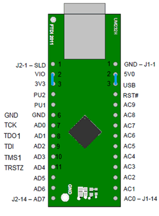
The DLPC900 JTAG Programmer Tool requires the UM232H module with modifications, which is manufactured by Future Technology Devices International Ltd (FTDI Chip), . The UM232H module can be purchased from Digi-key with the following part number: 768-1103-ND. The driver can be downloaded from the FTDI website (www.ftdichip.com). Select the VCP CDM WHQL Certified driver for Windows.
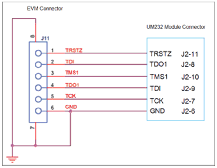
Make the following modifications to the UM232H and use Figure 4-27 and Figure 4-28 as a guide.
Connection Details
- BUS power configuration
- Short PIN #2 and PIN #3 of J1 (SYS PWR)
- Short PIN #2 and PIN #3 of J2 (I/O PWR)
- J2-6 → GND (PWR)
- J2-7 → TCK (OUTPUT)
- J2-8 → TDO1 (OUTPUT)
- J2-9 → TDI (INPUT)
- J2-10 → TMS1 (OUTPUT)
- J2-11 → TRSTZ (OUTPUT)
 Figure 4-27 UM232H Module
 Figure 4-28 UM232H Wiring Diagram
Choose the driver found in the CDM WHQL Certified zip folder and allow driver installation to complete. Install a jumper at J10/J12 for the DLP LightCrafter Dual DLPC900 EVM. Populate R118 with a 0 ohm resistor and depopulate R117 near the center of the main board. Connect the JTAG signals at J11 on the DLP LightCrafter Dual DLPC900 EVM to the UM232H module as shown in Figure 4-28. Finally, connect the UM232H to the PC with USB cable.
The JTAG programmer has a copy of the FlashDeviceParameters.txt file, which is located in the DLPC900REF-SW-x.x.x\\DLPC900REF-JTAG directory of the DLPC900REF-SW bundle. See Section 4.11 for instructions on how to edit this file to match the flash. If users have already made changes to the FlashDeviceParameters.txt file in the DLPC900REF-SW-x.x.x\DLPC900REF-GUI\Flash directory that work with the GUI, then users can copy that file to the DLPC900REF-SW-x.x.x\\DLPC900REF-JTAG directory
Start the DLPC900 Flash Programmer program and select the BoardFile.brd and the bootloader.bin included the install folder. Select USB as communication method from the Settings menu.
Power-up the EVM board and click the Detect Chain tool button. The tool detects the DLPC900 in JTAG chain and shows two DLPC900s. Now, click on one of the DLPC900 to select. On the EVM notice, the Red/Green LEDs light up (D6/D7 or D8/D9) to confirm which DLPC900 is currently selected.
Click the Flash Info button and confirm the correct flash part is detected by the tool. Using the Flash Erase button select the first sectors (to cover first 128 kilobytes) and erase these sectors.
Once sector erase is complete, set the Start Address (HEX) to 0x00000000 and set the Size (HEX) to 0x20000. Then click the Program Flash button, and then wait until write is complete.
Once the EVM is detected, go to the firmware page and select the primary and secondary image files for the attached DMD EVM and program them.