DLPU107 May 2022 DLP5532-Q1
2.1 Kit Assembly Instructions
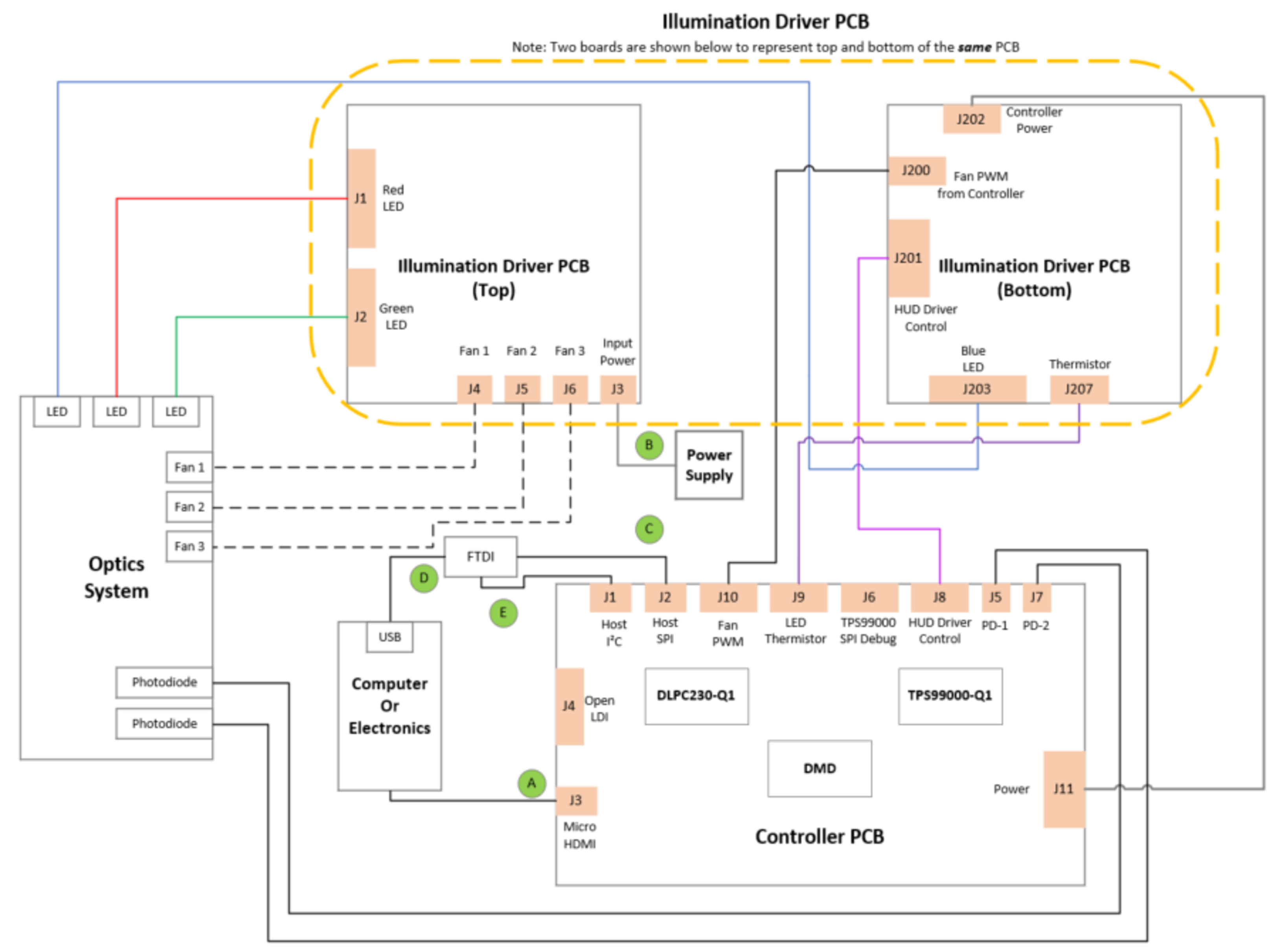
A diagram of all connections is shown in Figure 2-1.
- Connect the host SPI/I2C cable to the controller PCB (J2/J1) and the FTDI adapter. Connect the FTDI adapter’s USB cable to PC.
- Connect the Micro HDMI cable to the controller PCB (J3). Connect the Micro HDMI cable to PC HDMI port.
- Connect the power input cable to the illumination driver PCB (J3).
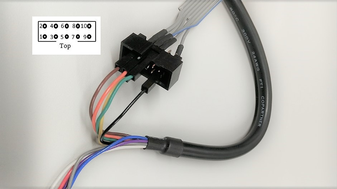 Figure 2-2 FTDI to SPI Cable Connection
For correct orientation of the numbering of leads notice that on the SPI cable there is a notch at the top. Note that there is some unused cables from the FTDI cable and unconnected pins on the SPI cable.
- Connect brown wire of FTDI cable (Chip Select) to pin 9 of SPI cable.
- Connect orange wire of FTDI cable (Clock) to pin 7 of SPI cable.
- Connect green wire of FTDI cable (Serial In) to pin 5 of SPI cable.
- Connect black wire of FTDI cable (Ground) to pin 2 of SPI cable.
- Connect yellow wire of FTDI cable (Serial Out) to pin 8 of SPI cable.
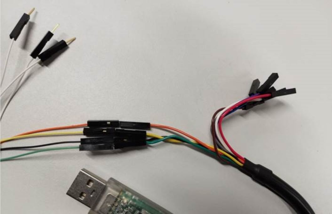 Figure 2-3 FTDI to I2C Connection
It is also possible to communicate with the EVM through I2C. Note that there is some unused cables from the FTDI cable and unused cables from the I2C cable.
- Connect orange wire of FTDI cable (Clock) to orange wire of I2C cable.
- Connect yellow wire of FTDI cable (Serial Out) to yellow wire of I2C cable.
- Connect black wire of FTDI cable (Ground) to black wire of I2C cable.
- Connect green wire of FTDI cable (Serial In) to green wire of I2C cable.
The following provide visual references for the fan cable connections involving the DLP5532PROJHBQ1EVM projector itself.
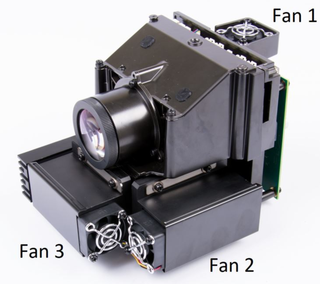 Figure 2-4 Fan Connection Cables
The following provide visual references for the LED cable connections involving the DLP5532PROJHBQ1EVM projector itself.
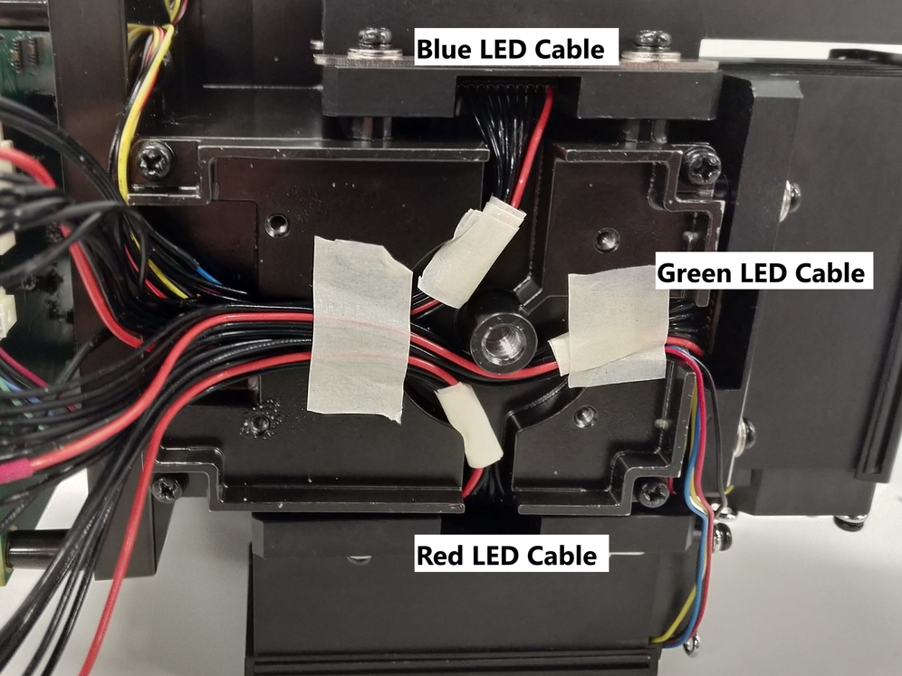
Please do not attempt to remove the four screws on the LED heat sinks as this impacts the alignment of the illumination system.
