DLPU108 May 2022 DLP5532-Q1
2.1 Kit Assembly Instructions
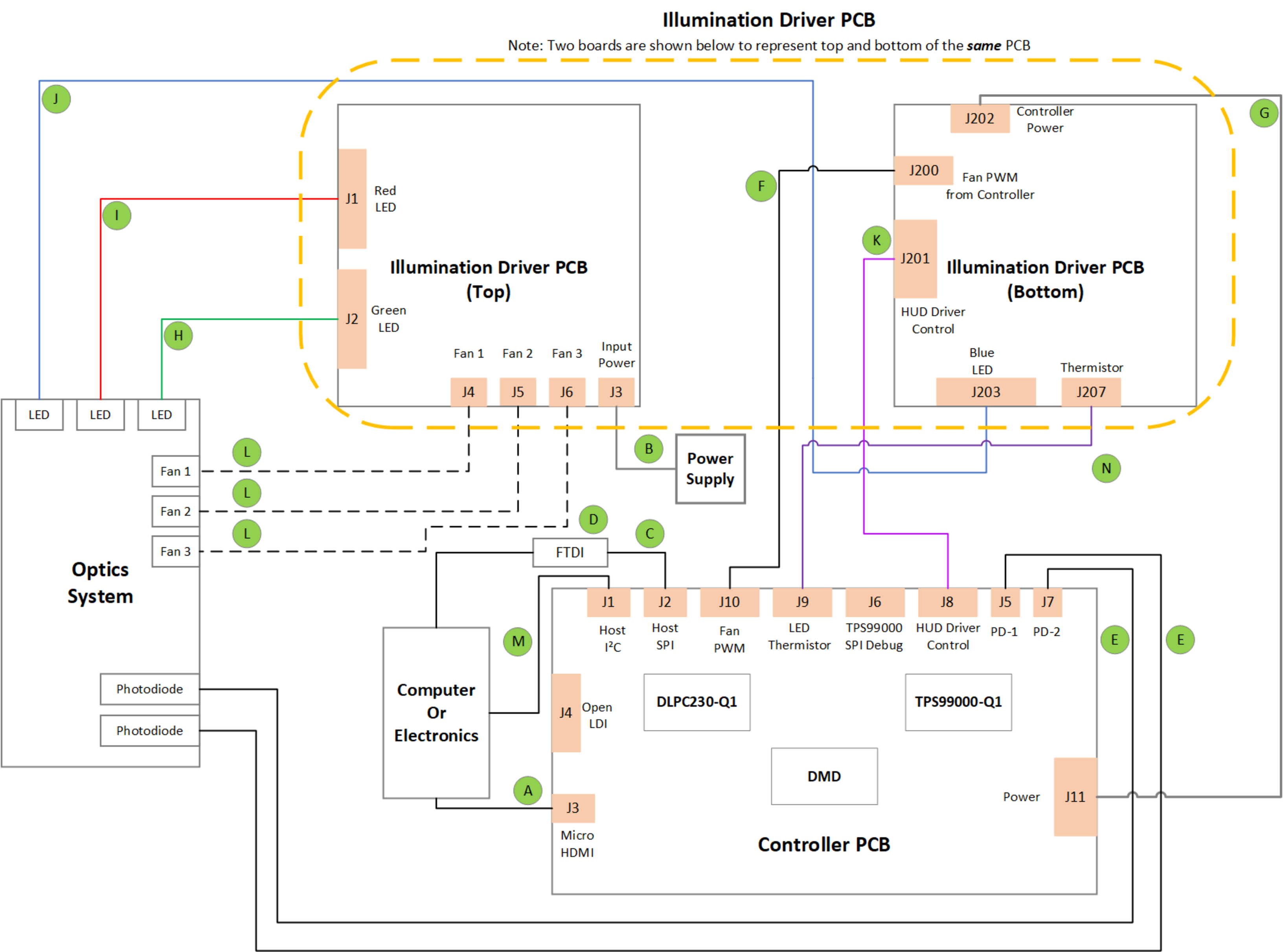
A diagram of all connections is shown in Figure 2-1.
- Connect the controller to driver control interface flex cable to the controller PCB (J8) and the illumination driver PCB (J201).
- Connect the host SPI /I2C cable to the controller PCB (J2/J1) and the FTDI adapter. Connect the FTDI adapter’s USB cable to PC.
- Connect the controller power cable to the controller PCB (J11) and the illumination driver PCB (J202).
- Connect the blue illumination output cable to the illumination driver PCB (J203) and then to the blue illuminator in the optics system.
- Connect the green illumination output cable to the illumination driver PCB (J2) and then to the green illuminator in the optics system.
- Connect the red illumination output cable to the illumination driver PCB (J1) and then to the red illuminator in the optics system.
- Connect the respective fan cables to the illumination driver PCB ports (J4, J5, J6) and then to the fans themselves in the optics system.
- Connect the photodiode cable to the controller PCB (J5) to a photodiode located in the illumination path of the optics system.
- Connect the Micro HDMI cable to the controller PCB (J3). Connect the Micro HDMI cable to PC HDMI port.
- Connect the power input cable to the illumination driver PCB (J3).
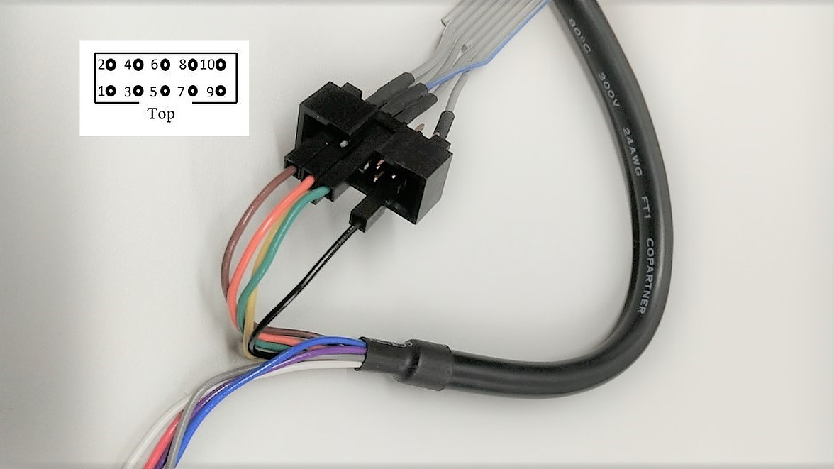
 Figure 2-2 FTDI to SPI Cable Connection
For correct orientation of the numbering of leads notice that on the SPI cable there is a notch at the top. Note that there is some unused cables from the FTDI cable and unconnected pins on the SPI cable.
- Connect brown wire of FTDI cable (Chip Select) to pin 9 of SPI cable.
- Connect orange wire of FTDI cable (Clock) to pin 7 of SPI cable.
- Connect green wire of FTDI cable (Serial In) to pin 5 of SPI cable.
- Connect black wire of FTDI cable (Ground) to pin 2 of SPI cable.
- Connect yellow wire of FTDI cable (Serial Out) to pin 8 of SPI cable.
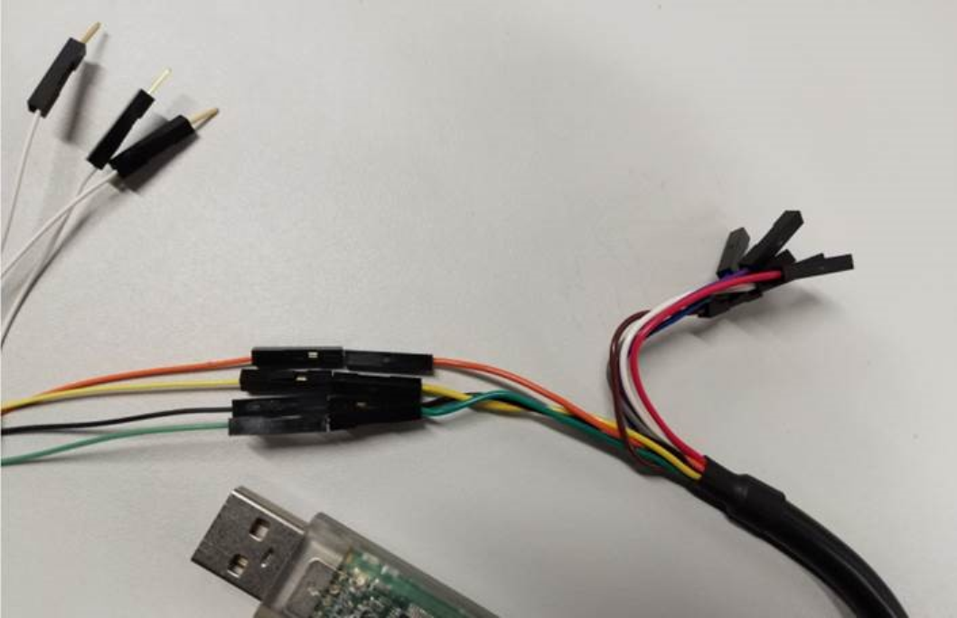
 Figure 2-3 FTDI to I2C Connection
It is also possible to communicate with the EVM through I2C. Note that there is some unused cables from the FTDI cable and unused cables from the I2C cable.
- Connect orange wire of FTDI cable (Clock) to orange wire of I2C cable.
- Connect yellow wire of FTDI cable (Serial Out) to yellow wire of I2C cable.
- Connect black wire of FTDI cable (Ground) to black wire of I2C cable.
- Connect green wire of FTDI cable (Serial In) to green wire of I2C cable.
