DLPU131A November 2023 – September 2024
1.3 DLPDLCR160CPEVM Subsystems
The DLP LightCrafter Display module consists of two subsystems:
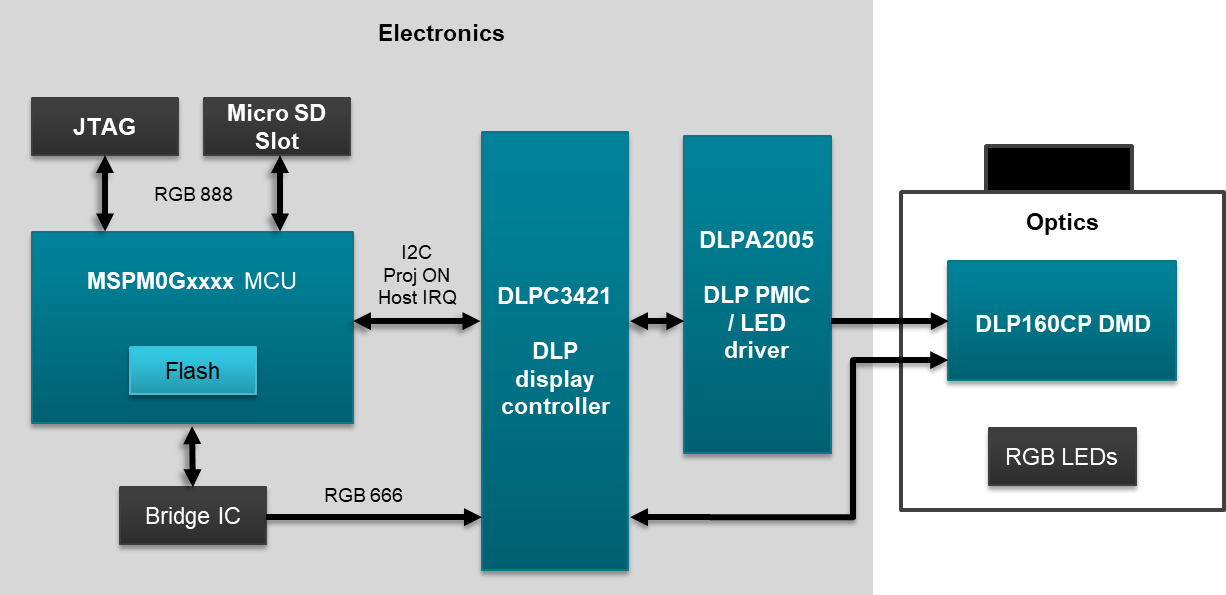
- Formatter Board: includes the DLP chipset (DLPC3421 display controller and DLPA2005 PMIC/LED driver). The MSPM0G3507 MCU, SSD1963 video interface driver, and Micro-SD card connector are also included.
- Light Engine: includes optics, RGB LEDs, and DLP160CP DMD displaying 640 × 360 pixels (nHD) on screen. See light engine subsystem description in the table below.
Table 1-1 EVM LED Currents and ANSI Lumens
| EVM Configuration | LED Currents (A) (Typ) | ANSI Lumens (Typ) | ||
|---|---|---|---|---|
| GUI Setting | Red | Green | Blue | |
| Default LED Current | 0.20 | 0.25 | 0.25 | 20 |
| Max LED Current | 0.30 | 0.40 | 0.40 | 32 |
The DLPDLCR160CPEVM is designed to operate at a maximum ambient temperature of 30°C. A block diagram of the DLPDLCR160CPEVM is shown in Figure 1-1.
 Figure 1-1 DLPDLCR160CPEVM Block Diagram