DLPU134 April 2024
2.1 UART Requirements
The UART digital communication is a controller-peripheral communication link in which the MSPM0 is a peripheral device only. The controller sets when the data transmission begins and ends. The peripheral does not transmit data back to the controller until the controller commands it. A logic 1 value on the UART interface is defined as a recessive value (weak pullup on the RXD pin). A logic 0 value on the UART interface is defined as a dominant value (strong pulldown on the RXD pin).
The UART asynchronous-mode interface is designed for data-rates from 2400bps to 115200bps operation. Other parameters related to the operation of the UART interface include:
- Baud rate from 2.4kbps to 115.2kbps. Default is 9.6kbps
- 8 data bits
- 1 start bit
- 1 stop bit
- No parity bit
- No flow control
- Interfield wait time (only required for 1 stop bit configuration)

Figure 2-1 UART Asynchronous Interface Bit Timing
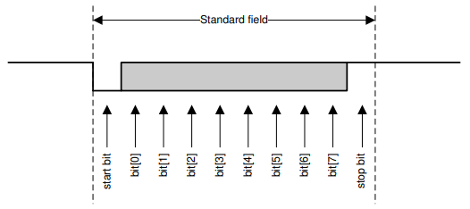
Both data and control are in little endian format. Data is transmitted through the UART interface in byte-sized packets. The first bit of the packet field is the start bit (dominant). The next 8 bits of the field are data bits to be processed by the UART receiver. The final bit in the field is the stop bit (recessive). The combined byte of information, and the start and stop bits make up an UART field.

Figure 2-2 UART Interface Packet Field
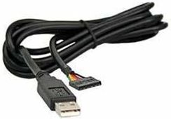
The TTL-232R-3V3 is a USB to Serial (TTL level) converter cable which allows for a simple way to connect TTL interface units to USB. This version of the FTDI USB to TTL serial adapter cables has the I/O pins configured to operate at 3.3V levels. This is an example USB to Serial device to use during testing.

Figure 2-3 USB to Serial Device