JAJSCJ6C September 2016 – October 2024 UCC28950-Q1 , UCC28951-Q1
PRODUCTION DATA
- 1
- 1 特長
- 2 アプリケーション
- 3 概要
- 4 Pin Configuration and Functions
- 5 Specifications
-
6 Detailed Description
- 6.1 Overview
- 6.2 Functional Block Diagram
- 6.3
Feature Description
- 6.3.1 Start-Up Protection Logic
- 6.3.2 Voltage Reference (VREF)
- 6.3.3 Error Amplifier (EA+, EA–, COMP)
- 6.3.4 Soft-Start and Enable (SS/EN)
- 6.3.5 Light-Load Power Saving Features
- 6.3.6 Adaptive Delay, (Delay Between OUTA and OUTB, OUTC and OUTD (DELAB, DELCD, ADEL))
- 6.3.7 Adaptive Delay (Delay Between OUTA and OUTF, OUTB and OUTE (DELEF, ADELEF)
- 6.3.8 Minimum Pulse (TMIN)
- 6.3.9 Burst Mode
- 6.3.10 Switching Frequency Setting
- 6.3.11 Slope Compensation (RSUM)
- 6.3.12 Dynamic SR ON/OFF Control (DCM Mode)
- 6.3.13 Current Sensing (CS)
- 6.3.14 Cycle-by-Cycle Current Limit Current Protection and Hiccup Mode
- 6.3.15 Synchronization (SYNC)
- 6.3.16 Outputs (OUTA, OUTB, OUTC, OUTD, OUTE, OUTF)
- 6.3.17 Supply Voltage (VDD)
- 6.3.18 Ground (GND)
- 6.4 Device Functional Modes
-
7 Application and Implementation
- 7.1 Application Information
- 7.2
Typical Application
- 7.2.1 Design Requirements
- 7.2.2
Detailed Design Procedure
- 7.2.2.1 Power Loss Budget
- 7.2.2.2 Preliminary Transformer Calculations (T1)
- 7.2.2.3 QA, QB, QC, QD FET Selection
- 7.2.2.4 Selecting LS
- 7.2.2.5 Selecting Diodes DB and DC
- 7.2.2.6 Output Inductor Selection (LOUT)
- 7.2.2.7 Output Capacitance (COUT)
- 7.2.2.8 Select FETs QE and QF
- 7.2.2.9 Input Capacitance (CIN)
- 7.2.2.10 Current Sense Network (CT, RCS, R7, DA)
- 7.2.3 Application Curves
- 7.3 Power Supply Recommendations
- 7.4 Layout
- 8 Device and Documentation Support
- 9 Revision History
- 10Mechanical, Packaging, and Orderable Information
3 概要
UCC28951-Q1 コントローラは UCC28950-Q1 の拡張版で、UCC28950-Q1 と完全に互換性のあるドロップイン代替品です。使用すべきコントローラを決定するには、アプリケーション ノート『UCC28950-Q1 と UCC28951-Q1 の正しい選び方』を参照します。UCC2895x-Q1 デバイスは、同期整流器 (SR) 出力段の能動制御に加えて、フルブリッジの先進制御を採用しています。
ZVS 動作はさまざまな動作条件で保証されており、負荷電流によって 2 次側同期整流器 (SR) のスイッチング遅延が自動的に調整されるため、システム全体の効率が最大化されます。
『UCC2895x-Q1 600W 位相シフト フルブリッジ設計レビュー / アプリケーション ノート』(SLUA560) を使って、気軽に設計を開始しましょう。
24 ピンの TSSOP パッケージは RoHS に準拠しています。
製品情報
| 部品番号 | パッケージ (1) | 本体サイズ (公称) |
|---|---|---|
| UCC2895x-Q1 | TSSOP (24) | 7.80mm × 4.40mm |
(1) 利用可能なすべてのパッケージについては、データシートの末尾にある注文情報を参照してください。
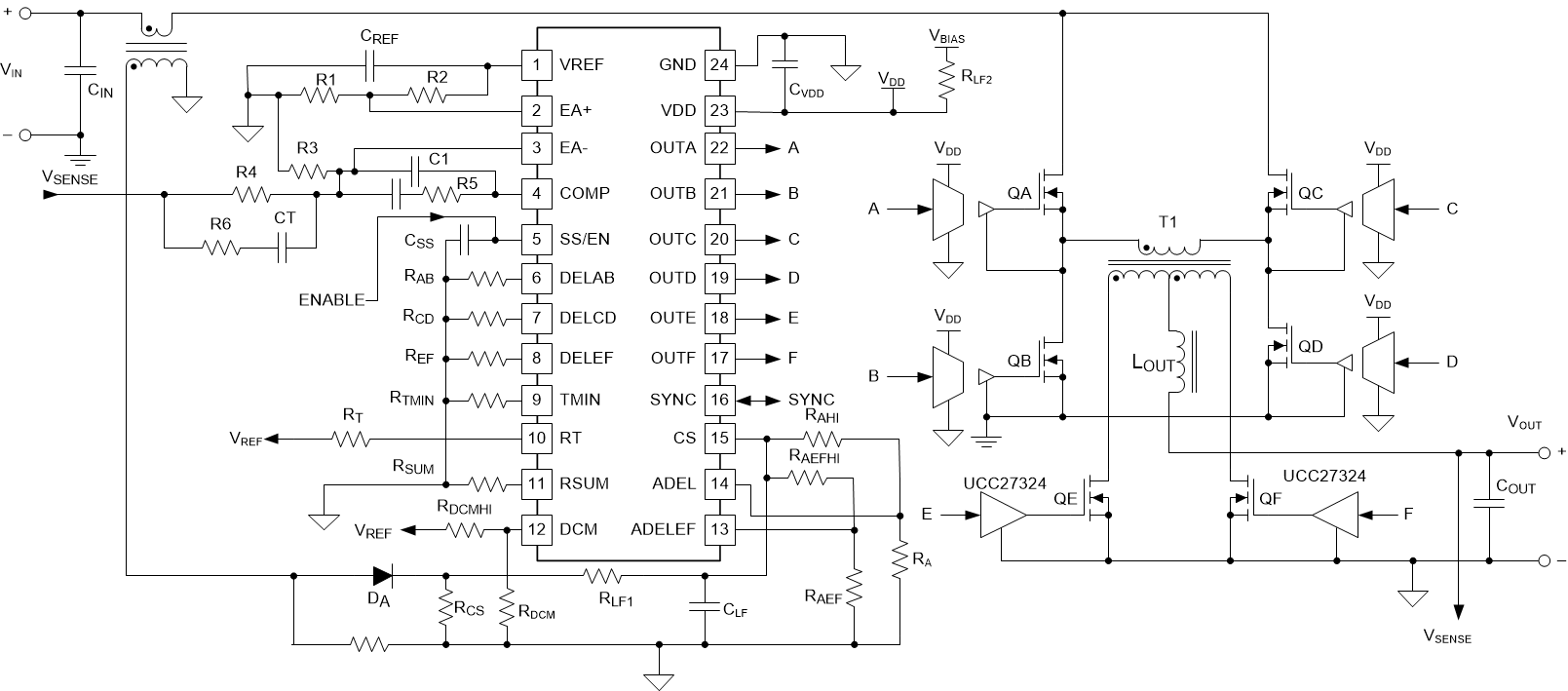
 アプリケーション概略図