-
TPS7A54-Q1 4A、高精度、車載グレード、低ノイズLDO電圧レギュレータ
- 1 特長
- 2 アプリケーション
- 3 概要
- 4 改訂履歴
- 5 Pin Configuration and Functions
- 6 Specifications
- 7 Detailed Description
-
8 Application and Implementation
- 8.1
Application Information
- 8.1.1 Recommended Capacitor Types
- 8.1.2 Soft Start and Inrush Current
- 8.1.3 Optimizing Noise and PSRR
- 8.1.4 Charge Pump Noise
- 8.1.5 Current Sharing
- 8.1.6 Adjustable Operation
- 8.1.7 Power-Good Operation
- 8.1.8 Undervoltage Lockout (UVLO) Operation
- 8.1.9 Dropout Voltage (VDO)
- 8.1.10 Device Behavior During Transition From Dropout Into Regulation
- 8.1.11 Load Transient Response
- 8.1.12 Reverse Current Protection Considerations
- 8.1.13 Power Dissipation (PD)
- 8.1.14 Estimating Junction Temperature
- 8.2 Typical Application
- 8.1
Application Information
- 9 Power Supply Recommendations
- 10Layout
- 11デバイスおよびドキュメントのサポート
- 12メカニカル、パッケージ、および注文情報
- 重要なお知らせ
DATA SHEET
TPS7A54-Q1 4A、高精度、車載グレード、低ノイズLDO電圧レギュレータ
このリソースの元の言語は英語です。 翻訳は概要を便宜的に提供するもので、自動化ツール (機械翻訳) を使用していることがあり、TI では翻訳の正確性および妥当性につきましては一切保証いたしません。 実際の設計などの前には、ti.com で必ず最新の英語版をご参照くださいますようお願いいたします。
1 特長
- 車載アプリケーションに対応
- 車載アプリケーション用にAEC-Q100認定済み
- 温度グレード1: -40℃≦TA≦+125℃
- HBM ESD分類レベル2
- CDM ESD分類レベルC4A
- 拡張接合部温度範囲(TJ): -40℃~+150℃
- 入力電圧範囲:
- BIASなし: 1.4V~6.5V
- BIASあり: 1.1V~6.5V
- 可変出力電圧範囲: 0.8V~ 5.1V
- 低いドロップアウト: 4A、BIASありで240mV (最大値)
- 出力電圧ノイズ: 4.4µVRMS
- ライン、負荷、温度範囲にわたって1% (最大値)の精度(BIAS使用時)
- 電源リップル除去:
- 500kHz時に40dB
- 可変のソフトスタート突入電流制御
- オープン・ドレインのパワー・グッド(PG)出力
- 3.5mm×3.5mmの20ピンVQFNパッケージ
2 アプリケーション
- テレマティクス制御ユニット
- インフォテインメントおよびクラスタ
- 高速インターフェイス(PLLおよびVCO)
3 概要
TPS7A54-Q1デバイスは低ノイズ(4.4µVRMS)、低ドロップアウトのリニア・レギュレータ(LDO)で、4Aを供給でき、ドロップアウトは最大でわずか240mVです。デバイスの出力電圧は、外付けの分圧抵抗によって0.8V~5.1Vの範囲で調整可能です。
低ノイズ(4.4µVRMS)、高PSRR、大出力電流の能力の組み合わせにより、TPS7A54-Q1はレーダーの電源やインフォテイメント・アプリケーションなどに使用される、電力ノイズに敏感な部品への電源供給に理想的です。このデバイスは高性能で、電源によって生成される位相ノイズとクロック・ジッタを制限するため、RFアンプ、レーダー・センサ、チップセットの電源として理想的です。特に、RFアンプにはこのデバイスの高い性能と5.0V出力能力が役立ちます。
ASIC (Application-Specific Integrated Circuit)、FPGA (Field-Programmable Gate Array)、DSP (Digital Signal Processor)などのデジタル負荷で低入力電圧、低出力(LILO)電圧の動作を必要とする場合、TPS7A54-Q1の非常に優れた精度(負荷および温度範囲にわたって1%)、リモート・センシング、優れた過渡性能、ソフトスタート機能によって、最適のシステム性能が保証されます。
多用途なTPS7A54-Q1デバイスは、要求の厳しい多くのアプリケーションの部品として最適な選択肢です。
製品情報(1)
| 型番 | パッケージ | 本体サイズ(公称) |
|---|---|---|
| TPS7A54-Q1 | VQFN (20) | 3.50mm×3.50mm |
- 利用可能なすべてのパッケージについては、このデータシートの末尾にあるパッケージ・オプションについての付録を参照してください。
Device Images
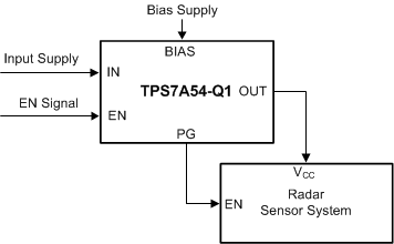
RFコンポーネントの電源

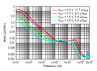
出力電圧ノイズと
周波数および出力電圧との関係

5 Pin Configuration and Functions
RGR Package
3.5-mm × 3.5-mm, 20-Pin VQFN
Top View
Pin Functions
| PIN | DESCRIPTION | ||
|---|---|---|---|
| NAME | NO. | I/O | |
| BIAS | 12 | I | BIAS supply voltage. This pin enables the use of low-input voltage, low-output (LILO) voltage conditions (that is, VIN = 1.2 V, VOUT = 1 V) to reduce power dissipation across the die. The use of a BIAS voltage improves dc and ac performance for VIN ≤ 2.2 V. A 10-µF capacitor or larger must be connected between this pin and ground. If not used, this pin must be left floating or tied to ground. |
| DNC | 5 | Do not connect | |
| EN | 14 | I | Enable pin. Driving this pin to logic high enables the device; driving this pin to logic low disables the device. If enable functionality is not required, this pin must be connected to IN or BIAS. |
| FB | 3 | I | Feedback pin connected to the error amplifier. Although not required, a 10-nF feed-forward capacitor from FB to OUT (as close to the device as possible) is recommended to maximize ac performance. The use of a feed-forward capacitor can disrupt PG (power good) functionality. |
| GND | 8, 18 | — | Ground pin. These pins must be connected to ground, the thermal pad, and each other with a low-impedance connection. |
| IN | 15-17 | I | Input supply voltage pin. A 10-µF or larger ceramic capacitor (5 µF or greater of capacitance) from IN to ground is recommended to reduce the impedance of the input supply. Place the input capacitor as close to the input as possible. |
| NC | 2, 6, 7, 9, 10, 11 | No internal connection | |
| NR/SS | 13 | — | Noise-reduction and soft-start pin. Connecting an external capacitor between this pin and ground reduces reference voltage noise and also enables the soft-start function. Although not required, a 10-nF or larger capacitor is recommended to be connected from NR/SS to GND (as close to the pin as possible) to maximize ac performance. |
| OUT | 1, 19, 20 | O | Regulated output pin. A 47-µF or larger ceramic capacitor (25 µF or greater of capacitance) from OUT to ground is required for stability and must be placed as close to the output as possible. Minimize the impedance from the OUT pin to the load. |
| PG | 4 | O | Active-high, power-good pin. An open-drain output indicates when the output voltage reaches VIT(PG) of the target. The use of a feed-forward capacitor may disrupt PG (power good) functionality. |
| Thermal pad | — | Connect the thermal pad to a large-area ground plane. The thermal pad is internally connected to GND. | |