JAJSF23B March 2018 – July 2018 INA1620
PRODUCTION DATA.
- 1 特長
- 2 アプリケーション
- 3 概要
- 4 改訂履歴
- 5 Pin Configuration and Functions
- 6 Specifications
- 7 Detailed Description
- 8 Application and Implementation
- 9 Power Supply Recommendations
- 10Layout
- 11デバイスおよびドキュメントのサポート
- 12メカニカル、パッケージ、および注文情報
7.3.4 EN Pin
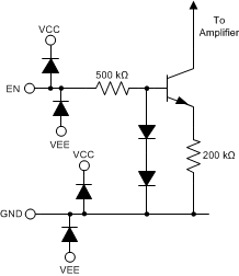
The enable pin (EN) of the INA1620 is used to toggle the amplifier enabled and disabled states. The logic levels defining these two states are: VEN ≤ 0.78 V (shutdown mode), and VEN ≥ 0.82 V (enabled). These threshold levels are referenced to the device ground (GND) pin. The EN pin can be driven by a GPIO pin from the system controller, discrete logic gates, or can be connected directly to the V+ supply. Do not leave the EN pin floating because the amplifier is prevented from being enabled. Likewise, do not place GPIO pins used to control the EN pin in a high-impedance state because this placement also prevents the amplifier from being enabled. A small current flows into the enable pin when a voltage is applied. Using the simplified internal schematic shown in Figure 46, use Equation 4 to estimate the enable pin current:

As illustrated in Figure 46, the EN pin is protected by diodes to the amplifier power supplies. Do not connect the EN pin to voltages outside the limits defined in the Specifications section.
 Figure 46. EN Pin Simplified Internal Schematic