JAJSGJ9A
November 2018 – May 2019
TPS56339
PRODUCTION DATA.
1
特長
2
アプリケーション
3
概要
Device Images
概略回路図
TPS56339 の効率
4
改訂履歴
5
Pin Configuration and Functions
Pin Functions
6
Specifications
6.1
Absolute Maximum Ratings
6.2
ESD Ratings
6.3
Recommended Operating Conditions
6.4
Thermal Information
6.5
Electrical Characteristics
6.6
Timing Requirements
6.7
Typical Characteristics
7
Detailed Description
7.1
Overview
7.2
Functional Block Diagram
7.3
Feature Description
7.3.1
Advanced Emulated Current Mode Control
7.3.2
Enable and Adjusting Undervoltage Lockout
7.3.3
Soft Start and Pre-Biased Soft Start
7.3.4
Voltage Reference
7.3.5
Minimum ON-time, Minimum OFF-time and Frequency Foldback at Dropout Conditions
7.3.6
Overcurrent and Undervoltage Protection
7.3.7
Thermal Shutdown
7.4
Device Functional Modes
7.4.1
Shutdown Mode
7.4.2
Active Mode
7.4.3
CCM Operation
7.5
Light-Load Operation
8
Application and Implementation
8.1
Application Information
8.2
Typical Application
8.2.1
Design Requirements
8.2.2
Detailed Design Procedure
8.2.2.1
Custom Design With WEBENCH® Tools
8.2.2.2
Output Voltage Resistors Selection
8.2.2.3
Output Inductor Selection
8.2.2.4
Output Capacitor Selection
8.2.2.5
Input Capacitor Selection
8.2.2.6
Bootstrap Capacitor Selection
8.2.3
Undervoltage Lockout Set Point
8.2.4
Application Curves
9
Power Supply Recommendations
10
Layout
10.1
Layout Guidelines
10.2
Layout Example
11
デバイスおよびドキュメントのサポート
11.1
ドキュメントの更新通知を受け取る方法
11.2
関連リンク
11.3
コミュニティ・リソース
11.4
商標
11.5
静電気放電に関する注意事項
11.6
Glossary
12
メカニカル、パッケージ、および注文情報
8.2.4
Application Curves
V
IN
= 12 V, L
1
= 5.6 µH, C
OUT
= 44 µF, T
A
= 25 °C. (unless otherwise noted)
Figure 18.
Efficiency
Figure 20.
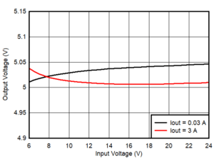
Line Regulation
A.
Figure 22.
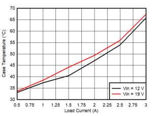
Case Temperature Rise vs Load Current
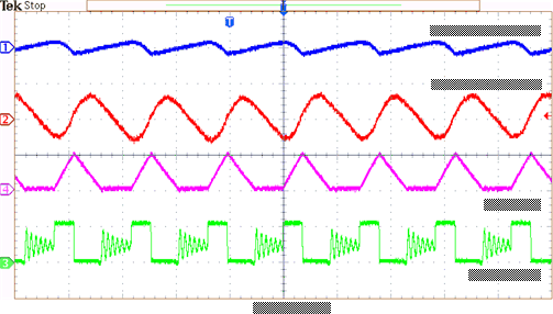
Figure 24.
Steady State Waveforms, I
OUT
= 0.3 A
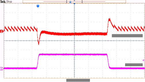
Figure 26.
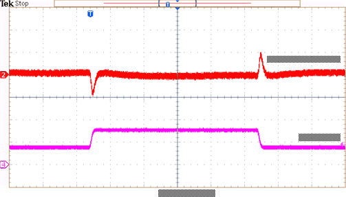
Transient Response 1.5 to 3 A
Figure 28.
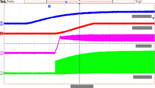
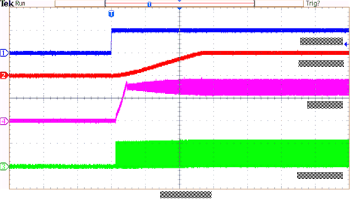
Startup Relative to V
IN
1.
Figure 30.
Enable Relative to EN
A.
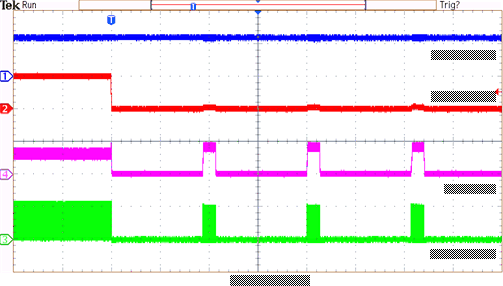
Figure 32.
Short Protection
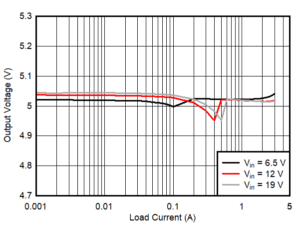
Figure 19.
Load Regulation
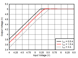
Figure 21.
Dropout Curve
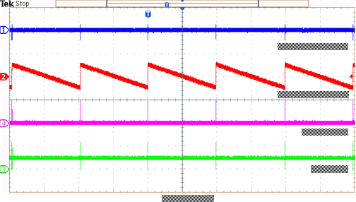
Figure 23.
Steady State Waveforms, I
OUT
= 0 A
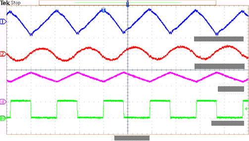
Figure 25.
Steady State Waveforms, I
OUT
= 3 A
Figure 27.
Transient Response 0.3 to 2.7 A
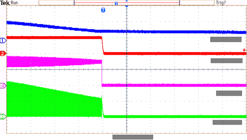
Figure 29.
Shutdown Relative to V
IN
1.
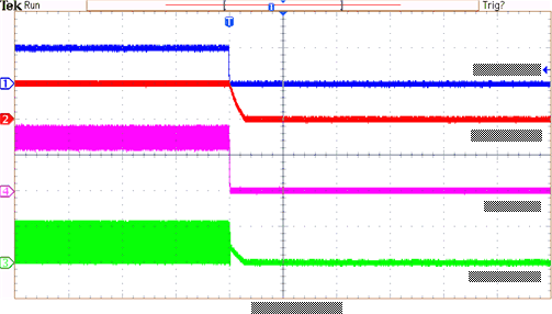
Figure 31.
Disable Relative to EN
A.
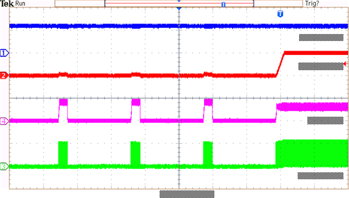
Figure 33.
Short Recovery