JAJSJG4B August   2020  – May 2024 LP8864S-Q1

PRODUCTION DATA  

  1.   1
  2. 特長
  3. アプリケーション
  4. 概要
  5. Pin Configuration and Functions
  6. Specifications
    1. 5.1 Absolute Maximum Ratings
    2. 5.2 ESD Ratings
    3. 5.3 Recommended Operating Conditions
    4. 5.4 Thermal Information
    5. 5.5 Electrical Characteristics
    6. 5.6 Logic Interface Characteristics
    7. 5.7 Timing Requirements for I2C Interface
    8.     14
    9. 5.8 Typical Characteristics
  7. Detailed Description
    1. 6.1 Overview
    2. 6.2 Functional Block Diagram
    3. 6.3 Feature Description
      1. 6.3.1 Control Interface
      2. 6.3.2 Function Setting
      3. 6.3.3 Device Supply (VDD)
      4. 6.3.4 Enable (EN)
      5. 6.3.5 Charge Pump
      6. 6.3.6 Boost Controller
        1. 6.3.6.1 Boost Cycle-by-Cycle Current Limit
        2. 6.3.6.2 Controller Min On/Off Time
        3. 6.3.6.3 Boost Adaptive Voltage Control
          1. 6.3.6.3.1 FB Divider Using Two-Resistor Method
          2. 6.3.6.3.2 FB Divider Using Three-Resistor Method
          3. 6.3.6.3.3 FB Divider Using External Compensation
        4. 6.3.6.4 Boost Sync and Spread Spectrum
        5. 6.3.6.5 Boost Output Discharge
        6. 6.3.6.6 Light Load Mode
      7. 6.3.7 LED Current Sinks
        1. 6.3.7.1 LED Output Current Setting
        2. 6.3.7.2 LED Output String Configuration
        3. 6.3.7.3 LED Output PWM Clock Generation
      8. 6.3.8 Brightness Control
        1. 6.3.8.1 Brightness Control Signal Path
        2. 6.3.8.2 Dimming Mode
        3. 6.3.8.3 LED Dimming Frequency
        4. 6.3.8.4 Phase-Shift PWM Mode
        5. 6.3.8.5 Hybrid Mode
        6. 6.3.8.6 Direct PWM Mode
        7. 6.3.8.7 Sloper
        8. 6.3.8.8 PWM Detector Hysteresis
        9. 6.3.8.9 Dither
      9. 6.3.9 Protection and Fault Detections
        1. 6.3.9.1 Supply Faults
          1. 6.3.9.1.1 VIN Undervoltage Faults (VINUVLO)
          2. 6.3.9.1.2 VIN Overvoltage Faults (VINOVP)
          3. 6.3.9.1.3 VDD Undervoltage Faults (VDDUVLO)
          4. 6.3.9.1.4 VIN OCP Faults (VINOCP)
            1. 6.3.9.1.4.1 VIN OCP Current Limit vs. Boost Cycle-by-Cycle Current Limit
          5. 6.3.9.1.5 Charge Pump Faults (CPCAP, CP)
          6. 6.3.9.1.6 CRC Error Faults (CRCERR)
        2. 6.3.9.2 Boost Faults
          1. 6.3.9.2.1 Boost Overvoltage Faults (BSTOVPL, BSTOVPH)
          2. 6.3.9.2.2 Boost Overcurrent Faults (BSTOCP)
          3. 6.3.9.2.3 LEDSET Resistor Missing Faults (LEDSET)
          4. 6.3.9.2.4 MODE Resistor Missing Faults (MODESEL)
          5. 6.3.9.2.5 FSET Resistor Missing Faults (FSET)
          6. 6.3.9.2.6 ISET Resistor Out of Range Faults (ISET)
          7. 6.3.9.2.7 Thermal Shutdown Faults (TSD)
        3. 6.3.9.3 LED Faults
          1. 6.3.9.3.1 Open LED Faults (OPEN_LED)
          2. 6.3.9.3.2 Short LED Faults (SHORT_LED)
          3. 6.3.9.3.3 LED Short to GND Faults (GND_LED)
          4. 6.3.9.3.4 Invalid LED String Faults (INVSTRING)
          5. 6.3.9.3.5 I2C Timeout Faults
        4. 6.3.9.4 Overview of the Fault and Protection Schemes
    4. 6.4 Device Functional Modes
      1. 6.4.1  State Diagram
      2. 6.4.2  Shutdown
      3. 6.4.3  Device Initialization
      4. 6.4.4  Standby Mode
      5. 6.4.5  Power-line FET Soft Start
      6. 6.4.6  Boost Start-Up
      7. 6.4.7  Normal Mode
      8. 6.4.8  Fault Recovery
      9. 6.4.9  Latch Fault
      10. 6.4.10 Start-Up Sequence
    5. 6.5 Programming
      1. 6.5.1 I2C-Compatible Interface
      2. 6.5.2 Programming Examples
        1. 6.5.2.1 General Configuration Registers
        2. 6.5.2.2 Clearing Fault Interrupts
        3. 6.5.2.3 Disabling Fault Interrupts
        4. 6.5.2.4 Diagnostic Registers
  8. Register Maps
    1. 7.1 FullMap Registers
  9. Application and Implementation
    1. 8.1 Application Information
    2. 8.2 Typical Applications
      1. 8.2.1 Full Feature Application for Display Backlight
        1. 8.2.1.1 Design Requirements
        2. 8.2.1.2 Detailed Design Procedure
          1. 8.2.1.2.1  Inductor Selection
          2. 8.2.1.2.2  Output Capacitor Selection
          3. 8.2.1.2.3  Input Capacitor Selection
          4. 8.2.1.2.4  Charge Pump Output Capacitor
          5. 8.2.1.2.5  Charge Pump Flying Capacitor
          6. 8.2.1.2.6  Output Diode
          7. 8.2.1.2.7  Switching FET
          8. 8.2.1.2.8  Boost Sense Resistor
          9. 8.2.1.2.9  Power-Line FET
          10. 8.2.1.2.10 Input Current Sense Resistor
          11. 8.2.1.2.11 Feedback Resistor Divider
          12. 8.2.1.2.12 Critical Components for Design
        3. 8.2.1.3 Application Curves
      2. 8.2.2 Application with Basic/Minimal Operation
        1. 8.2.2.1 Design Requirements
        2. 8.2.2.2 Detailed Design Procedure
        3. 8.2.2.3 Application Curves
      3. 8.2.3 SEPIC Mode Application
        1. 8.2.3.1 Design Requirements
        2. 8.2.3.2 Detailed Design Procedure
          1. 8.2.3.2.1  Inductor Selection
          2. 8.2.3.2.2  Coupling Capacitor Selection
          3. 8.2.3.2.3  Output Capacitor Selection
          4. 8.2.3.2.4  Input Capacitor Selection
          5. 8.2.3.2.5  Charge Pump Output Capacitor
          6. 8.2.3.2.6  Charge Pump Flying Capacitor
          7. 8.2.3.2.7  Switching FET
          8. 8.2.3.2.8  Output Diode
          9. 8.2.3.2.9  Switching Sense Resistor
          10. 8.2.3.2.10 Power-Line FET
          11. 8.2.3.2.11 Input Current Sense Resistor
          12. 8.2.3.2.12 Feedback Resistor Divider
          13. 8.2.3.2.13 Critical Components for Design
        3. 8.2.3.3 Application Curves
    3. 8.3 Power Supply Recommendations
    4. 8.4 Layout
      1. 8.4.1 Layout Guidelines
      2. 8.4.2 Layout Example
  10. Device and Documentation Support
    1. 9.1 Device Support
      1. 9.1.1 サード・パーティ製品に関する免責事項
    2. 9.2 ドキュメントの更新通知を受け取る方法
    3. 9.3 サポート・リソース
    4. 9.4 Trademarks
    5. 9.5 静電気放電に関する注意事項
    6. 9.6 用語集
  11. 10Revision History
  12. 11Mechanical, Packaging, and Orderable Information

概要

LP8864S-Q1 は昇圧コントローラを備えた車載用、高効率の LED ドライバです。4 つの高精度電流シンクは、使用しているチャネル数に応じて自動調整される位相シフトをサポートしています。LED の輝度は、I²C インターフェイスまたは PWM 入力によりグローバルに制御できます。

この昇圧コントローラは、LED 電流シンクのヘッドルーム電圧に基づいた適応型出力電圧制御機能を備えています。この機能により、すべての条件で、必要最低限のレベルに昇圧を調整することで消費電力を最小化できます。周波数を広範囲に調整できるため、LP8864S-Q1 は AM ラジオ周波数帯に対する妨害を回避できます。

LP8864S-Q1 は組み込みのハイブリッド PWM 調光とアナログ電流調光をサポートしているため、EMI の削減、LED の寿命の延長、総合的な光学効率の向上を実現できます。

製品情報
部品番号 (1) パッケージ 本体サイズ (公称)
LP8864S-Q1 HTSSOP (38) 9.70mm × 4.40mm
QFN (32) 5mm × 5mm
利用可能なすべてのパッケージについては、データシートの末尾にある注文情報を参照してください。
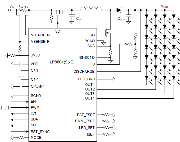
LP8864S-Q1 概略回路図概略回路図
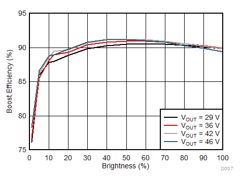
LP8864S-Q1 システム効率システム効率