JAJSLN2 November   2021 TPS7H1210-SEP

PRODUCTION DATA  

  1. 特長
  2. アプリケーション
  3. 概要
  4. Revision History
  5. Pin Configuration and Functions
  6. Specifications
    1. 6.1 Absolute Maximum Ratings
    2. 6.2 ESD Ratings
    3. 6.3 Recommended Operating Conditions
    4. 6.4 Thermal Information
    5. 6.5 Electrical Characteristics
    6. 6.6 Typical Characteristics
  7. Detailed Description
    1. 7.1 Overview
    2. 7.2 Functional Block Diagram
    3. 7.3 Feature Description
      1. 7.3.1 Internal Current Limit
      2. 7.3.2 Enable Pin Operation
      3. 7.3.3 Programmable Soft-Start
      4. 7.3.4 Thermal Protection
    4. 7.4 Device Functional Modes
      1. 7.4.1 Normal Operation
      2. 7.4.2 Dropout Operation
      3. 7.4.3 Disabled
  8. Application and Implementation
    1. 8.1 Application Information
      1. 8.1.1 Adjustable Operation
      2. 8.1.2 Capacitor Recommendations
      3. 8.1.3 Noise Reduction and Feed-Forward Capacitor Requirements
      4. 8.1.4 Power-Supply Rejection Ratio (PSRR)
      5. 8.1.5 Output Noise
      6. 8.1.6 Transient Response
      7. 8.1.7 Post DC-DC Converter Filtering
      8. 8.1.8 Power for Precision Analog
    2. 8.2 Typical Application
      1. 8.2.1 Design Requirements
      2. 8.2.2 Detailed Design Procedure
      3. 8.2.3 Application Curves
    3. 8.3 Do's and Don’ts
  9. Power Supply Recommendations
  10. 10Layout
    1. 10.1 Layout Guidelines
      1. 10.1.1 Improve PSRR and Noise Performance
    2. 10.2 Layout Example
    3. 10.3 Thermal Performance
  11. 11Device and Documentation Support
    1. 11.1 Device Support
      1. 11.1.1 Development Support
        1. 11.1.1.1 Spice Models
    2. 11.2 Documentation Support
      1. 11.2.1 Related Documentation
    3. 11.3 ドキュメントの更新通知を受け取る方法
    4. 11.4 サポート・リソース
    5. 11.5 Trademarks
    6. 11.6 静電気放電に関する注意事項
    7. 11.7 用語集
  12. 12Mechanical, Packaging, and Orderable Information

Enable Pin Operation

The TPS7H1210-SEP provides a dual-polarity enable pin (EN) that turns on the regulator when |VEN| > 2 V, whether the voltage is positive or negative, as shown in #SBVS125IMG7364. Specifically, if VEN ≥ VEN(+HI) or VEN ≤ VEN(–HI), the regulator is enabled. If VEN(+LO) ≥ VEN ≥ VEN(–LO), the regulator is disabled.

This functionality allows for different system power management topologies; for example:

  • Connecting the EN pin directly to a negative voltage, such as VIN.
  • Connecting the EN pin directly to a positive voltage, such as the output of digital logic circuitry.
  • Connecting the EN pin to a resistor divider from VIN to GND to turn-on at a specific input voltage level (programmable turn-on voltage).
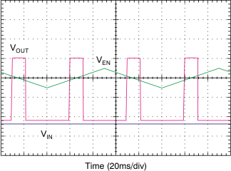
GUID-7AFF3FDC-86BA-4016-8F10-563E0EBFB1F9-low.gifFigure 7-1 Enable Pin Positive and Negative Threshold