JAJSMH3B December   1997  – November 2024 OPA134 , OPA2134 , OPA4134

PRODUCTION DATA  

  1.   1
  2. 特長
  3. アプリケーション
  4. 概要
  5. Pin Configuration and Functions
  6. Specifications
    1. 5.1 Absolute Maximum Ratings
    2. 5.2 ESD Ratings
    3. 5.3 Recommended Operating Conditions
    4. 5.4 Thermal Information - OPA134
    5. 5.5 Thermal Information - OPA2134
    6. 5.6 Thermal Information - OPA4134
    7. 5.7 Electrical Characteristics
    8. 5.8 Typical Characteristics
  7. Detailed Description
    1. 6.1 Overview
    2. 6.2 Feature Description
      1. 6.2.1 Total Harmonic Distortion
      2. 6.2.2 Distortion Measurements
      3. 6.2.3 Source Impedance and Distortion
      4. 6.2.4 Phase Reversal Protection
      5. 6.2.5 Output Current Limit
    3. 6.3 Functional Block Diagram
    4. 6.4 Device Functional Modes
      1. 6.4.1 Noise Performance
  8. Application and Implementation
    1. 7.1 Application Information
      1. 7.1.1 Operating Voltage
      2. 7.1.2 Offset Voltage Trim
    2. 7.2 Typical Application
      1. 7.2.1 Design Requirements
      2. 7.2.2 Detailed Design Procedure
      3. 7.2.3 Application Curve
    3. 7.3 Power Supply Recommendations
    4. 7.4 Layout
      1. 7.4.1 Layout Guidelines
      2. 7.4.2 Layout Example
  9. Device and Documentation Support
    1. 8.1 Device Support
      1. 8.1.1 Development Support
        1. 8.1.1.1 Analog Filter Designer
        2. 8.1.1.2 TINA-TI™シミュレーション ソフトウェア (無償ダウンロード)
        3. 8.1.1.3 TI のリファレンス・デザイン
    2. 8.2 Documentation Support
      1. 8.2.1 Related Documentation
    3. 8.3 ドキュメントの更新通知を受け取る方法
    4. 8.4 サポート・リソース
    5. 8.5 Trademarks
    6. 8.6 静電気放電に関する注意事項
    7. 8.7 用語集
  10. Revision History
  11. 10Mechanical, Packaging, and Orderable Information

Source Impedance and Distortion

For lowest distortion with a source or feedback network with an impedance greater than 2kΩ, match the impedance seen by the positive and negative inputs in noninverting applications. The p-channel JFETs in the FET input stage exhibit a varying input capacitance with applied common-mode input voltage. In inverting configurations, the input does not vary with input voltage, because the inverting input is held at virtual ground. However, in noninverting applications the inputs do vary, and the gate-to-source voltage is not constant. The effect is increased distortion due to the varying capacitance for unmatched source impedances greater than 2kΩ.

To maintain low distortion, match unbalanced source impedance with the appropriate values in the feedback network as shown in Figure 6-2. Of course, the unbalanced impedance can be from gain-setting resistors in the feedback path. If the parallel combination of R1 and R2 is greater than 2kΩ, use a matching impedance on the noninverting input. As always, minimize resistor values to reduce the effects of thermal noise.
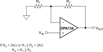
OPA134 OPA2134 OPA4134 Impedance
                    Matching for Maintaining Low Distortion in Noninverting Circuits Figure 6-2 Impedance Matching for Maintaining Low Distortion in Noninverting Circuits