JAJU316G November 2016 – April 2020
6.2 Project Structure
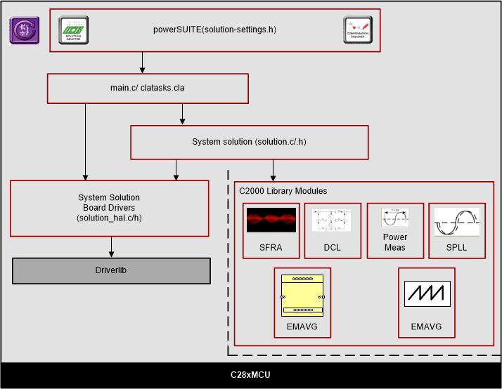
Figure 18 shows the general structure of the project.

NOTE
Figure 18 shows the project for F2837x; however, if a different device is chosen from the powerSUITE page, the structure is similar.
Solution specific and device independent files are <solution>.c/h. Board-specific and device-specific files are <solution>_hal.c/h. The main.c file of the project consists of the main function of the C project as well as ISR framework and calls routines in other files. <solution>_settings.h and <solution>_user_settings.h consist of all the settings required for the solution. <solution>_user_settings.h
For this design, <solution> is vienna.
<solution>_clatask.cla file include the CLA Task definitions.
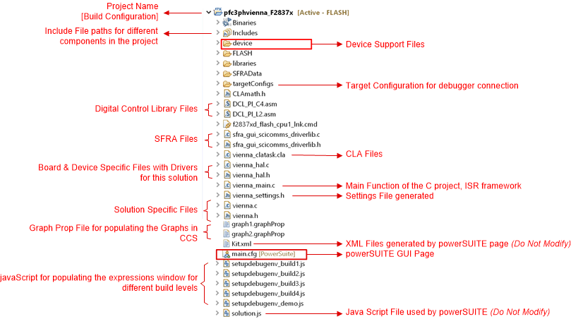
The powerSUITE page can be opened by clicking the main.syscfg file, listed below the project explorer. The powerSUITE page generates the <solution>_settings.h file. This file is the only file used in the compile of the project that is generated by the powerSUITE page. The user must not modify this file manually, as the changes will be overwritten by powerSUITE each time the project is rebuilt. The changes will only happen after rebuilding the entire project
TheKit.json and solution.js files are used internally by the powerSUITE and must also not be modified by the user. Any changes to these files will result in the project not functioning properly.
When the project is imported, the project explorer appears inside CCS as shown in Figure 19.

The project consists of an interrupt service routine, which is called every PWM cycle, called controlISR(), where the control algorithm is executed. In addition to this, there are background tasks A0-A4 and B0-B4, which are called in a polling fashion and can be used to run slow tasks for which absolute timing accuracy is not required. A slower 10-kHz routine tenkHzISR() is called for instrumentation and to run some slower tasks that require timing accuracy.
The software of this design guide is organized in four incremental builds (INCR_BUILD). The incremental build process simplifies the system bring up and design.
- INCR_BUILD 1: Open Loop Check
- INCR_BUILD 2: Closed Current Loop
- INCR_BUILD 3: Closed Voltage and Current Loop
- INCR_BUILD 4: Closed Voltage, Current, and Bus Cap Balance Loop
These build levels are detailed in the section below. If using the design guide hardware, make sure the hardware setup is completed as outlined in Section 5.