JAJU316G November 2016 – April 2020
6.4.3 INCR_BUILD 3: Closed Voltage and Current Loop
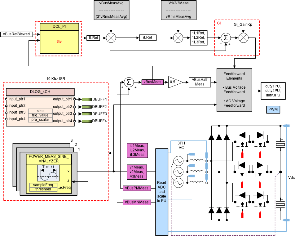
In this build the outer voltage loop is closed with the inner current loop closed (designed in BUILD 2). The model of the outer voltage loop was derived in Figure 36. A PI-based compensator is used and tuned through the Compensation Designer. Figure 36 shows the software diagram for this build.
Figure 36. Build Level 3 Control Diagram: Output Voltage Control With Inner Current Loop Figure 1. Build Level 3 Control Diagram: Output Voltage Control With Inner Current Loop
 Figure 1. Build Level 3 Control Diagram: Output Voltage Control With Inner Current Loop