JAJU657 December   2018


  1.    概要
  2.    リソース
  3.    特長
  4.    アプリケーション
  5.    デザイン・イメージ
  6. 1System Description
    1. 1.1 Key System Specifications
    2. 1.2 Introduction
    3. 1.3 MSP430FR2633 CapTIvate MCU
  7. 2System Overview
    1. 2.1 Block Diagram
    2. 2.2 Design Considerations
    3. 2.3 Highlighted Products
      1. 2.3.1 MSP430FR2633 MCU Block Diagram
      2. 2.3.2 CapTIvate Technology Block Diagram
  8. 3Hardware, Software, Testing Requirements, and Test Results
    1. 3.1 System Design Theory
    2. 3.2 Capacitive Touch Sensors
      1. 3.2.1 Wheel Sensor
      2. 3.2.2 Slider Sensor
      3. 3.2.3 Button Sensor
    3. 3.3 Gesture and Key Mapping
      1. 3.3.1 Media Player
      2. 3.3.2 USB HID Keyboard Data
    4. 3.4 Capacitive Touch Gestures
      1. 3.4.1 How Gesture Detection Works
      2. 3.4.2 Tap Gesture
      3. 3.4.3 Double-Tap Gesture
      4. 3.4.4 Tap-and-Hold Gesture
      5. 3.4.5 Swipe Gesture
      6. 3.4.6 Slide Gesture
    5. 3.5 Getting Started With Hardware
    6. 3.6 Getting Started With Firmware
      1. 3.6.1 Programming Target MCU
      2. 3.6.2 MSP430FR2633 CapTIvate Gesture Firmware
      3. 3.6.3 Memory Footprint
      4. 3.6.4 MSP430F5529 HID Keyboard Device Firmware
    7. 3.7 Testing
      1. 3.7.1 Gesture
      2. 3.7.2 Power Measurements
      3. 3.7.3 Moisture Tolerance
  9. 4Demonstration
    1. 4.1 Wheel
      1. 4.1.1 Volume Control
      2. 4.1.2 Changing Music Tracks
        1. 4.1.2.1 Play/Pause
      3. 4.1.3 Mute
    2. 4.2 Slider
      1. 4.2.1 Volume Control
      2. 4.2.2 Changing Music Tracks
      3. 4.2.3 Play or Pause
      4. 4.2.4 Mute
    3. 4.3 Buttons
      1. 4.3.1 Volume Control
      2. 4.3.2 Changing Music Tracks
      3. 4.3.3 Play or Pause
      4. 4.3.4 Mute
  10. 5Design Files
    1. 5.1 Schematic
    2. 5.2 Bill of Materials
  11. 6Software Files
  12. 7Related Documentation
    1. 7.1 商標
  13. 8Terminology
  14. 9About the Author

MSP430FR2633 MCU Block Diagram

MSP430FR2633 MCUs feature a diverse peripheral set that makes them ideal for use in many capacitive sensing applications. Figure 2 shows the block diagram of the MSP430FR2633 MCU.
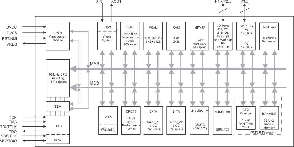
TIDM-02004 SLAS942_Functional_Block_Diagram.gifFigure 2. Block Diagram of MSP430FR2633